There are numerous descriptions of Arduino controlled car projects available on the internet. Kits are available complete with motors and chassis. Some of these kits are two wheel drive with the third wheel as a floating castor.
This three wheel configuration is inherently unstable and will not drive in a straight line, even if both motors are set to the same speed in the driving program. Variations in wheel diameter, rolling friction and motor characteristics will cause deviations. The only way to overcome this is to add feedback and apply corrections to the motor speeds at regular intervals. This project will explain how this can be implemented to allow for straight driving.
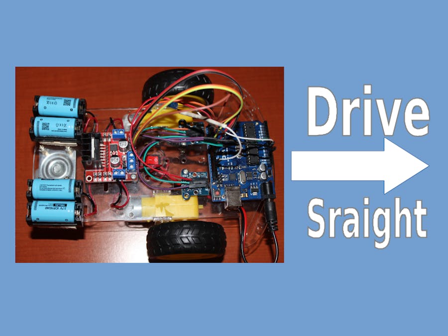
The Arduino Controlled CarHere is an example of an Arduino controlled car, built from a two wheel drive kit. The principal components are:
Two wheel drive kit including motors, chassis, various screws and nuts, wheels and wheel encoders.
- Arduino UNO
- L298N Motor driver bridge board
- 2 x HC-020K Encoder Module
- 4 x ICR16340 Lithium ion batteries and holders
- Toggle on/off switch
- Connection wires
This article does not include a description of how to build the car; there are many resources on the internet that explain the required steps.
Completed Car below:
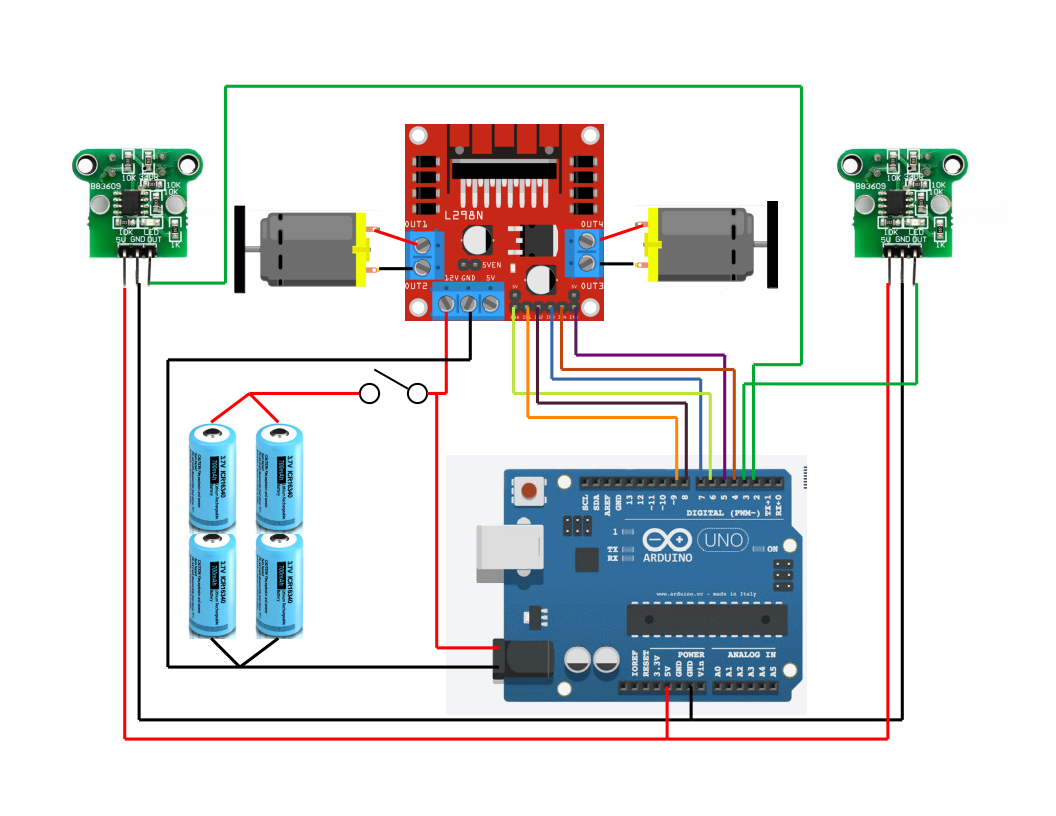
Circuit diagram of the completed car below:
Just a points to note on the configuration:
- The car uses four ICR16340 700 mAh Lithium ion batteries in a parallel/series configuration. Two of these cells in series provide about 8 V when fully charged, which is enough to drive the motors and Arduino board. Connecting batteries in parallel is potentially problematic (you can get circulating currents), as an alternative the ICR16340 batteries come in a 2800 mAh version – two of these in series should be sufficient to power the car.
- Motor control is carried out by a L298N bridge driver module. Again, plenty of resources that explain how they operate and how to connect motors and controls.
- This circuit uses digital pins 5 and 6 for the PWM output to the L298N board to control motor speed. The PWM frequency of these pins is controlled via timer 0 of the ATmega328P. PWM frequency of digital pins 9 and 10 are controlled by timer 1. Later on in this project, timer1 is used to trigger a distance control loop and so conflicts with PWM from pins 9 and 10. Don't use these pins in this project.
- Depending on how your specific wiring is completed, motor leads may have to be swapped to get consistent direction. In addition, the HC-020K Encoder Module must be paired with the correct motor in the software. This may require swapping interrupt 2 and 3 around or adjusting the software.
The HC-020K Encoder Module relies on a LM393 comparator to generate square wave pulses. Every hole in the encoder wheel causes a rising edge and falling edge in the square wave whose frequency is then proportional to wheel speed. Counting these square wave pulses also gives a total which is proportional to distance traveled. The standard way to count these pulses using the Arduino is to connect them to an interrupt and have a interrupt service routine (ISR) increment a counter (sample code later).
Several experiments which tried to reconcile pulse count with rpm and distance traveled showed that the pulse count was incorrect by a factor of about ten – ten times to many pulses. This makes the encoders pretty much useless. This anomaly needed further investigation
Here are some oscilloscope traces of the HC-020K Encoder:
At the 5ms timescale, the rising and falling edges of the square wave look clean. However, if you zoom up to a time scale of 2micro seconds, the falling edge of the square wave shows multiple up down spikes during the 5V to 0V transition.
Each of these spikes are potentially triggering an interrupt and resulting in over count of pulses. They are cause by the nature of the comparator circuit on the HC-020K Encoder Module – it operates in open loop mode.
The correct way to solve this problem is to introduce hysteresis into the comparator circuit by adding a feedback resistor between the output and the voltage divider that provides the reference voltage. There are several articles that explain this circuit – here is an example from Texas Instruments.
https://www.ti.com/lit/ug/tidu020a/tidu020a.pdf
To modify the HC-020K Encoder Module for hysteresis requires a 50KOhm resistor from the output to pin 2 of the LM393. It is practically very difficult to carry out this mod because of the surface mount IC used. If you can do it – good luck!
Some additional research showed an alternative approach. This requires a 100nF capacitor between the output and ground. This is an easier mod to achieve and is shown below.
The capacitor effectively filters out the high frequency spikes and provides a smooth transition. The resulting wave is not square because it is modified by the capacitor charging and discharging on the leading and falling edges. An oscilloscope trace as follows:
Zoom to a time scale of 5 micro seconds, the falling edge of the square wave shows a single transition
After this modification, the pulse count lines up well with the rpm observed.
Feedback ControlNow that the mystery of to many pulses has been solved, it is time to apply feedback control from the wheel encoders to the motor speed. The basic idea is to adjust individual motor speed based on the number of pulses measured so that the wheels cover the same distance and drive the Arduino in a straight line.
Feedback control loops fall into many categories, but the most common are called PID (Proportional, Integral and Derivative) loops. There is a lot of information on this topic and their study is a whole academic discipline. Simple system shown below:
The set point (desired output) is compared to the feedback (actual output) and the error is used to generate an input into the system under control. This input drives the system to the desired output so that ultimately the feedback equals the set point.
In the case of the Arduino car, the output that needs to be controlled is the difference between the pulse counts from the two wheels. If this difference is zero, the wheels will have traveled the same distance (assuming wheel diameters are equal).
A few definitions:
- Pulse count from wheel A (motor A) = pulseA
- Pulse count from wheel B (motor B) = pulseB
- Difference between pulse counts = Feedback = pError = pulseA – pulseB
- Set Point = 0
Here is a flowchart of the basic control strategy for the Arduino car:
The controlling program on the Arduino uses interrupts for two purposes:
- To count the pulses from the encoders. Each time the encoder output makes a 1 to 0 transistion, an interrupt is triggered on the Arduino.
- To force a control loop to compare the pulses counted and adjust motor speed according to the control algorithm.
The relevant code snippet for the first interrupt is
const int encoder1 = 2;
const int encoder2 = 3;
volatile int pulse1;
volatile int pulse2;

void setup(){
  pulse1 = 0;
  pulse2 = 0;

  attachInterrupt(digitalPinToInterrupt(encoder1), count1, FALLING);
  attachInterrupt(digitalPinToInterrupt(encoder2), count2, FALLING);
}

void count1(){
  // counting the number of pulses for encoder 1
  pulse1++;
}

void count2(){
  // counting the number of pulses for encoder 2
  pulse2++;
Pins 2 and 3 are used for the interrupt input from the encoders. pulse1 and pulse2 are variables used to hold the count. Count1 and count2 are the interrupt service routines and merely increment the counters. The interrupts are triggered on the falling edge of the square wave received from the encoder.
The second interrupt uses Timer1 that is built into the ATMega328. The timer triggers an interrupt at a predetermined interval. This then runs a control loop that keeps the car driving straight. Relevant code snippet as follows:
void setup(){

cli();//stop interrupts

  //set timer1 interrupt at 4Hz
  TCCR1A = 0;// set entire TCCR1A register to 0
  TCCR1B = 0;// same for TCCR1B
  TCNT1  = 0;//initialize counter value to 0
  // set compare match register for 4hz increments
  OCR1A = 3905;// = (16*10^6) / (4*1024) - 1 (must be <65536)
  // turn on CTC mode
  TCCR1B |= (1 << WGM12);
  // Set CS12 and CS10 bits for 1024 prescaler
  TCCR1B |= (1 << CS12) | (1 << CS10);
  // enable timer compare interrupt
  TIMSK1 |= (1 << OCIE1A);

  sei();//allow interrupts

}

ISR(TIMER1_COMPA_vect){

//Control loop here

}
The prescaler (0CR1A) value determines the frequency of the interrupts.
Controlling the car (Part 1)The first approach to driving the car straight uses a simple algorithm based on the flow chart. Code below:
 int pError = 0;
pError = pulse1 - pulse2;

 // pError is positive speed up motor A and slow down motor B
 if(pError > 0){
  analogWrite(enA, (motorSpeed + 7));
  analogWrite(enB, (motorSpeed - 7));
 }

 // pError is negative speed up motor B and slow down motor A
 else if(pError < 0){
  analogWrite(enA, (motorSpeed - 7));
  analogWrite(enB, (motorSpeed + 7));
 }

 else {
  analogWrite(enA, motorSpeed);
  analogWrite(enB, motorSpeed);
 }

 digitalWrite(led, toggle);
toggle = !toggle;A more sophisticated approach uses a PID controller. Arduino libraries include a library called FastPID which implements a PID controller. Add to libraries associated with the IDE.
Documentation on how to use this library at the following link
https://github.com/mike-matera/FastPID
Here is the code snippet
float Kp=0.6, Ki=0.4, Kd=0, Hz=4;
int output_bits = 8;
bool output_signed = false;

FastPID driveStraight(Kp, Ki, Kd, Hz, output_bits, output_signed);
ISR(TIMER1_COMPA_vect){
  static int pError;
  pError = 0;
  pError = pulse1 - pulse2;
  uint8_t output = driveStraight.step(setpoint, pError);

  analogWrite(enA, (motorSpeed - output));
  analogWrite(enB, (motorSpeed + output));

  digitalWrite(led,toggle);
  toggle = !toggle;
}
The sensitivity of the loop can be adjusted by assigning different values to Kp, Kd and Ki
Final WordsHopefully this helps straight driving!


_ztBMuBhMHo.jpg?auto=compress%2Cformat&w=48&h=48&fit=fill&bg=ffffff)


_3u05Tpwasz.png?auto=compress%2Cformat&w=40&h=40&fit=fillmax&bg=fff&dpr=2)


Comments
Please log in or sign up to comment.