I had a bunch of ATtiny85 chips laying around and reels of NeoPixel strips, so I decided I wanted to make something bright and colourful for my kids....
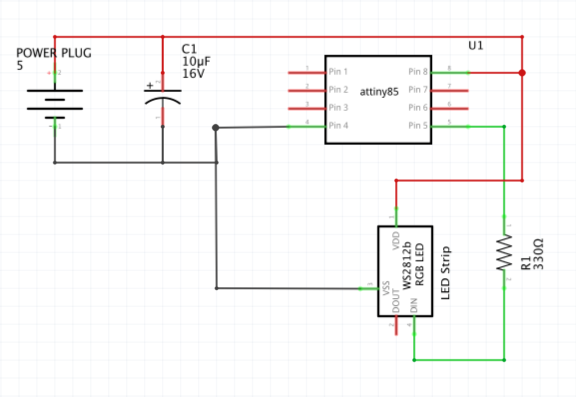
The full build process is in the video but I have included some additional diagrams below to help with the component placement and using the ATtiny85 in the Arduino IDE.
I have also included design files for a laser cut base and a 3D printed base, but I also show in the video that you could easily build a base for the display out of foam-board.
The build steps are pretty straight forward...
Steps- Cut the Protoboard to size
- Solder on the 8 pin IC socket
- Solder on the 2.1mm power cable
- Solder on the 10uF Capacitor
- Solder on the 330ohm Resistor
- Solder wires between the strip of 4 Neopixels and the PCB
- Make sure all GND and PWR pins are bridged
The you need to program your ATtiny85 with any neopixel library code you want.
To use the ATtiny85 in the Arduino IDE, you will need to add the following board link to the Additional Boards Manager URLs area of the Arduino IDE Preferences..
https://raw.githubusercontent.com/damellis/attiny/ide-1.6.x-boards-manager/package_damellis_attiny_index.json
Once that has been added, you will need to add the ATTiny Board Files from the Board Manager...
I hope you enjoy this project and decide to take on the challenge of making it or something similar!
You can check out the rest of my projects & videos at... unexpectedmaker.com
Follow me on Twitter, Facebook, Instagram & Tindie.
That's it!
Seon


_3u05Tpwasz.png?auto=compress%2Cformat&w=40&h=40&fit=fillmax&bg=fff&dpr=2)
Comments
Please log in or sign up to comment.