


Hardware components | ||||||
 |
| × | 1 | |||
 |
| × | 3 | |||
 |
| × | 2 | |||
 |
| × | 4 | |||
 |
| × | 1 | |||
 |
| × | 1 | |||
 |
| × | 1 | |||
 |
| × | 1 | |||
Software apps and online services | ||||||
 |
| |||||
| ||||||
We wanted to add a door monitor into our monitoring and automation system which seems simple....
The problem always becomes power, as running our board constantly even in a low power mode will run the battery down if left a long time (and depending on the door you fit it to it may be waiting a while).
So we need a solution which would consume nothing when off, and only stay on as long as needed to send our messaging.
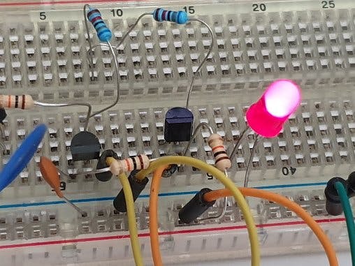
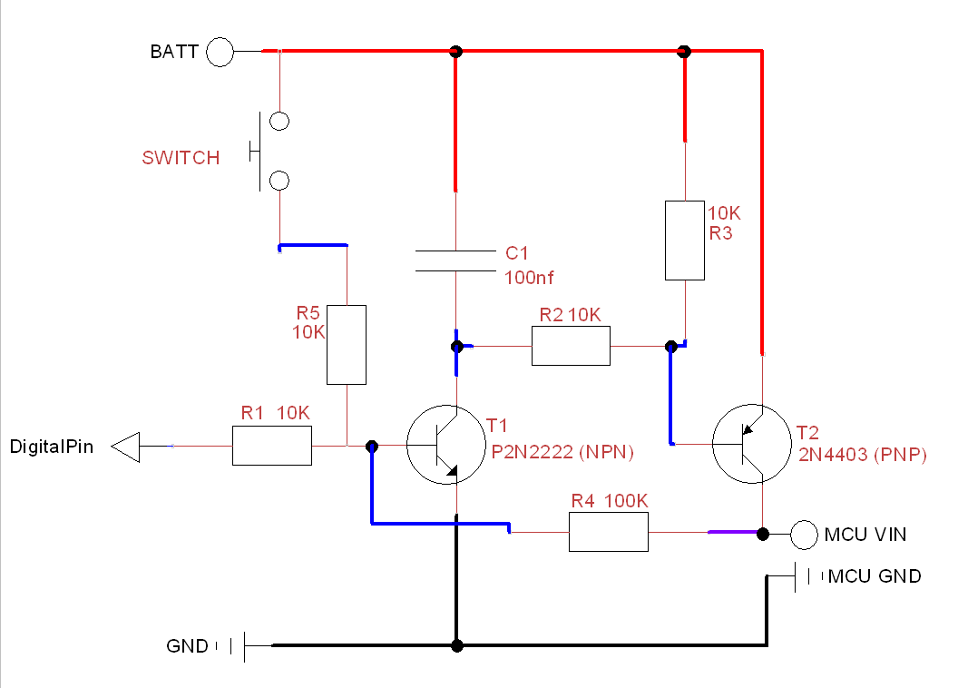
General HardwareThe part that does all the work here is actually a latching switch which we have created using a transistor latch circuit. A small latching relay could also be used to do the same job.
The switch will need to trigger both ways around (so we can log open and closed).
To do this we need the door to go beyond the switch slightly when it is shut, so the switch is pressed and released as the door opens / closes.
The CircuitNOTE - check the power rating of your board and the power input. Check the power being sunk from the Digital Pin is within your tolerances (we get around 5v from our batteries, and only need to sink 0.7v to turn the circuit off)
Coding for the CircuitAs our board will be truly off when powered down, we need to store our state in EEPROM, which is accessed via FlashStorage on the Nano33 IoT.
To power down the whole circuit simply run pull the pin LOW (connected to Digital Pin on the diagram) to power down the circuit. Next time the switch is triggered, it will power up our board again to repeat via the momentary switch.
In our project we were sending a message to a server, but as you can see this could fit any project, with the addition of the standard EEPROM Libraries and a simple write from any pin to turn the circuit off.
Using Visual Micro with Arduino this only takes a few clicks to add the libraries, and other code.
Try It OutOnce you have the code on the board and it all wired up, give it a go.
Then its just a case of deciding which door you want to know about.....

Comments
Please log in or sign up to comment.