This is a BreakoutBros.com tutorial. See the full post here.
Last week we looked into using the Particle Photon to connect to our RFID badge and LCD system using an Arduino to control an IoT device. But what about the other way around? This article we will discuss using an IoT device to control an Arduino.
Level ShiftersTo do this we will be expanding on the 5V to 3.3V level shifter we made in the Photon RFID article and also create a 3.3V to 5.5V level shifter. Instead of using the Digital I/O pins and sending pin state data we will be utilizing the UART serial ports of the Photon and Arduino.
The level shifting to the Photon was a necessity because 5V directly on the Photon pins put stress on the pins that could damage or degrade the chip.
When going from the Photon to the Arduino, level shifting is just as important. The Photon’s 3.3V won’t put extra stress on the Arduino pins but there is a different problem. The internal workings of the Arduino’s pins require a certain amount of voltage to register a “High”. If you do not exceed this voltage you can get intermittent false reads and corrupted data. Because of this, it is best to convert the 3.3V signal to a 5V signal so the Arduino will properly register the difference between “Highs” and “Lows”. Not using the level shifter may still work, but your project will have more of a chance to get corrupted data.
Parts Used- 10K resistor*
- 2k resistor*
- Wires and Breadboard*
*Note you can get these off amazon or any electronics store or you can check out one of the Arduino Starter Kits that will include these basic components.
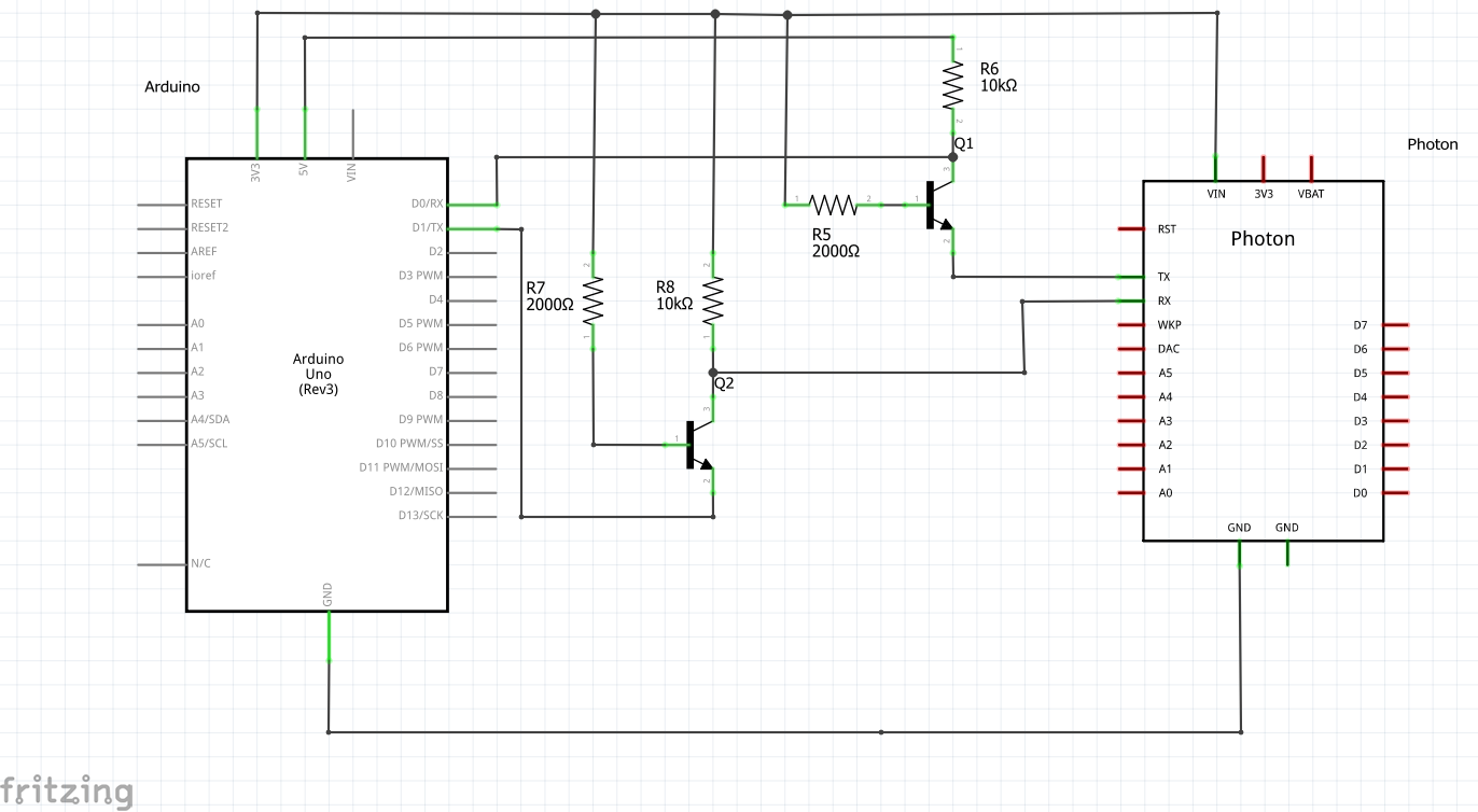
Just like for the 5V to 3.3V level shifting circuit, the 3.3V to 5.5V level shifting circuit will use the same parts, just in a different configuration. This level shifter will take the Particle Photons 3.3V output and shift it to 5V for the Arduino to correctly read data.
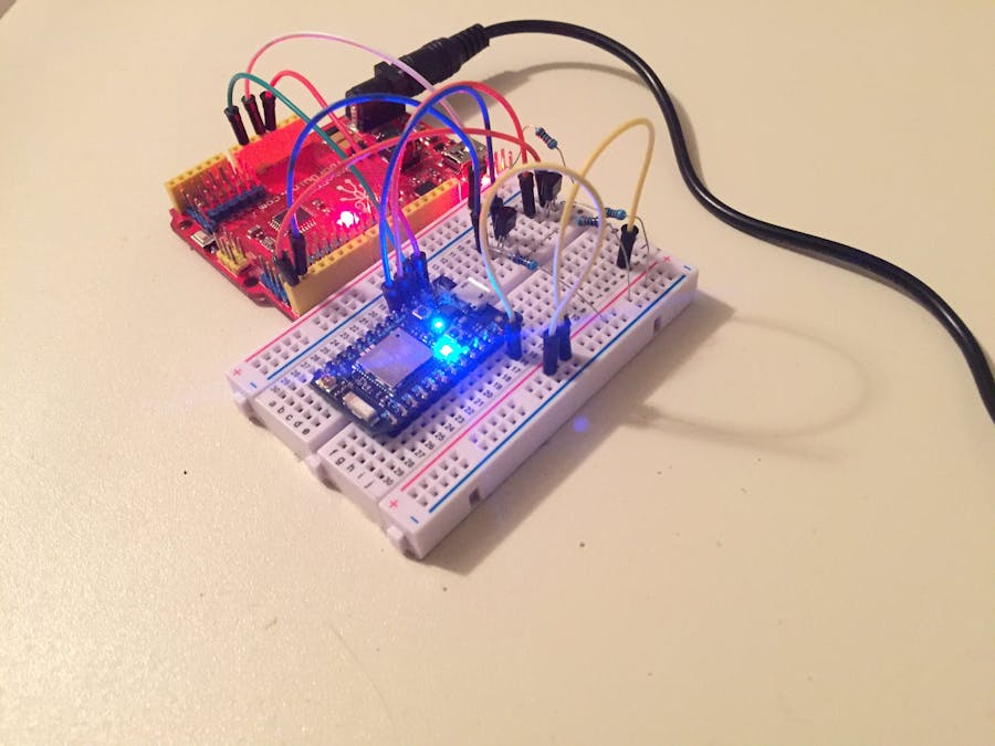
Wire the level shifters onto the bread board and connect the Arduino and Photon Particle as shown.
Login to your Particle account and go to the Photon’s IDE. We will create a simple program on the Photon that sends data over UART that will be used to turn on and off LEDs on the Ardunio. The built in Photon LED will also mimic these commands. That way you can quickly see if the Arduino is following the Photons commands.
//BreakoutBros tutorial
//Visit www.breakoutbros.com for more information
//ControlArduinoWifi_Arduino

//This tutorial will transmit Serial Data read from the Arduino
//It will flash the LED once at 1 second and 2 times at 1/4 a second

int led1 = D7;

void setup() {

  pinMode(led1, OUTPUT);
  pinMode(0, INPUT);
  pinMode(1, OUTPUT);
  digitalWrite(led1, LOW);
  Serial1.begin(9600);

}
//To communicate to the Arduino we will use the Serial1.write command
//The data will be sent over the UART to the arduino
//This will be a simple demo with the data being used to either
//turn on or turn off the Arduino LED. We will also turn on the
//photon LED to mimick this
void loop() {

  digitalWrite(led1, LOW);
  Serial1.write(0);
  delay(1000);
  digitalWrite(led1, HIGH);
  Serial1.write(1);
  delay(250);
  digitalWrite(led1, LOW);
  Serial1.write(0);
  delay(250);
  digitalWrite(led1, HIGH);
  Serial1.write(1);
  delay(200);
  digitalWrite(led1, LOW);
  Serial1.write(0);
  delay(1000);
  digitalWrite(led1, HIGH);
  Serial1.write(1);
  delay(1000);

}
Go ahead and upload this onto your Photon. The light should start blinking in the pattern that we set in the code – one 1 second flash and two 1/4 second flashes. Download the full Photon code here.
Arduino CodeNow that the Particle Photon is setup, let’s get the Arduino setup to pull for commands to follow the Photon’s blinking pattern. This code will run its main loop as long as there is data in the UART serial buffer and it will store this data to a variable. If the variable is equal to 0, the LED will turn off and if the variable is equal to 1, the LED will turn on.
//BreakoutBros tutorial
//Visit www.breakoutbros.com for more information
//ControlArduinoWifi_Arduino

//This tutorial will pull for the Serial Data from the Photon
//Depending on the data it recieves it will turn on or off it's LED

void setup() {
  pinMode(13, OUTPUT); //Set the LED pin as an output
  pinMode(0,INPUT); //Set the RX pin of the arduino as an input
  pinMode(1,OUTPUT); //Set the TX pin of the arduino as an output
  Serial.begin(9600); //Start the UART Serial communication
  delay(2000); // Wait 2 seconds - this allows the photon to power up as well before the Arduino trying to take commands
}
void loop() {
  while(Serial.available()>0) // if anything is in the Serial Buffer, run this code
  {
  Data = Serial.read(); // Read whats in the Serial buffer and store to DATA
  }
  if(Data == 0) // If the Data  is 0, turn off the LED
  {
    digitalWrite(13,LOW);
  }
  else if(Data == 1) // If the Data is 1 turn on the LED
  {
    digitalWrite(13,HIGH);
  }
}
Now upload this onto the Arduino. Make sure you disconnect the TX and RX pins while you do this – there can be errors in the programming of the code since the USB to your computer is also using these pins to program to the Arduino.
If everything works correctly you should see the Particle LED pulse and the Arduino LED follow it. As shown in the video below you can disconnect the Arduino TX and RX pins and to show that the Arduino stops following. Download the full Arduino code here.
Now we have it, a Particle Photon IoT device controlling an Arduino to follow an LED blinking pattern. Stay tuned as we expand on this and make sure you subscribe to get the latest updates on our latest posts.


_ztBMuBhMHo.jpg?auto=compress%2Cformat&w=48&h=48&fit=fill&bg=ffffff)


Comments
Please log in or sign up to comment.