

Hardware components | ||||||
| × | 1 | ||||
Software apps and online services | ||||||
 |
| |||||
In this tutorial, we'll delve into programming the STM32 "Black Pill" development board through STM32CubeIDE to generate various LED blinking sequences.
Materials Required:- STM32 Black Pill board
- USB to Mini-USB cable for both programming and power supply
- Three LEDs
- Breadboard and jumper wires
- STM32CubeIDE (Available for download and installation from the STMicroelectronics website)
Step 1: Startingup
Launch STM32CubeIDE and initiate a new project.
- Choose "New STM32 Project" from the Quick Start menu.
- Select your board or microcontroller (STM32F103C8) and proceed.
- Specify project name and location, then complete the setup.
- Launch STM32CubeIDE and initiate a new project.Choose "New STM32 Project" from the Quick Start menu.Select your board or microcontroller (STM32F103C8) and proceed.Specify project name and location, then complete the setup.
- In STM32CubeIDE, navigate to the "Pinout & Configuration" section.
- Configure three GPIO pins to control LEDs (e.g., GPIOA Pin 0, Pin 1, Pin 2 for Red, Green, Blue LEDs).
- Set these pins as GPIO Outputs and activate GPIO clock.
- Navigate to the "Core" directory in the project explorer and access main.c.
- Include necessary libraries and set up the initial environment.
- Code is given below: HAL_GPIO_WritePin(GPIOA, GPIO_PIN_5, 0);
HAL_GPIO_WritePin(GPIOA, GPIO_PIN_6, 0);
HAL_GPIO_WritePin(GPIOA, GPIO_PIN_7, 0);
HAL_Delay(1000);
HAL_GPIO_WritePin(GPIOA, GPIO_PIN_7, 1);
HAL_Delay(1000);
HAL_GPIO_WritePin(GPIOA, GPIO_PIN_6, 1);
HAL_GPIO_WritePin(GPIOA, GPIO_PIN_7, 0);
HAL_Delay(1000);
HAL_GPIO_WritePin(GPIOA, GPIO_PIN_6, 1);
HAL_GPIO_WritePin(GPIOA, GPIO_PIN_7, 1);
HAL_Delay(1000);
HAL_GPIO_WritePin(GPIOA, GPIO_PIN_5, 1);
HAL_GPIO_WritePin(GPIOA, GPIO_PIN_6, 0);
HAL_GPIO_WritePin(GPIOA, GPIO_PIN_7, 0);
HAL_Delay(1000);
HAL_GPIO_WritePin(GPIOA, GPIO_PIN_7, 1);
HAL_Delay(1000);
HAL_GPIO_WritePin(GPIOA, GPIO_PIN_6, 1);
HAL_GPIO_WritePin(GPIOA, GPIO_PIN_7, 0);
HAL_Delay(1000);
HAL_GPIO_WritePin(GPIOA, GPIO_PIN_6, 1);
HAL_GPIO_WritePin(GPIOA, GPIO_PIN_7, 1);
HAL_Delay(1000);
Step 4: Building and Flashing the Project- Connect your STM32 Black Pill board to your computer using a USB cable.
- Build the project by clicking on the hammer icon in the toolbar.
- Upon successful build, proceed to flash the code onto the board by clicking the play (debug) button.
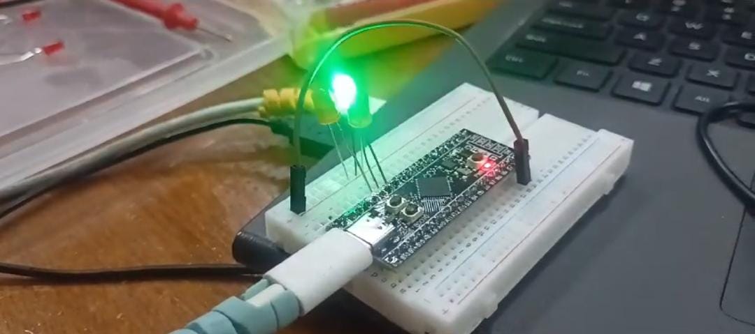
- Once flashing is complete, observe the LED blinking patterns exhibited by your Black Pill board.
- LEDs will blink in accordance with the defined patterns within the main loop.
Conclusion By following these steps, you've effectively programmed your STM32 Black Pill board to orchestrate LEDs in diverse blinking sequences using STM32CubeIDE. For further exploration, consider introducing new patterns or tweaking the existing code to create more intricate LED arrangements.


Comments