Burglar !!
Imagine this: You have gone out of the house (or have a vault built), and some burglar steals the valuables stored in your house / vault.
You do have CCTV cameras installed, but the footage is of little use since all the valuables are gone.
To prevent this, I have designed a usable, cheap Laser Security System using Bolt IoT, which just needs an internet connection and electric supply. (along with a server)
When the laser gets blocked, the buzzer will start buzzing and at that moment, a Telegram message is sent to you, notifying you of the break-in. And you can alert the authorities.
A small video showing the working :
(When the door is opened in the video, the laser gets cut off and the buzzer starts and a telegram message is sent)
Building Instructions: (Follow these steps very carefully)Note: The circuit connections image along with the code required to make this project work is attached at the end of the project.
Step 1: Gather the components
- Register your Bolt WiFi Module to the Bolt Cloud.
- Note your API Key and Bolt Device Number
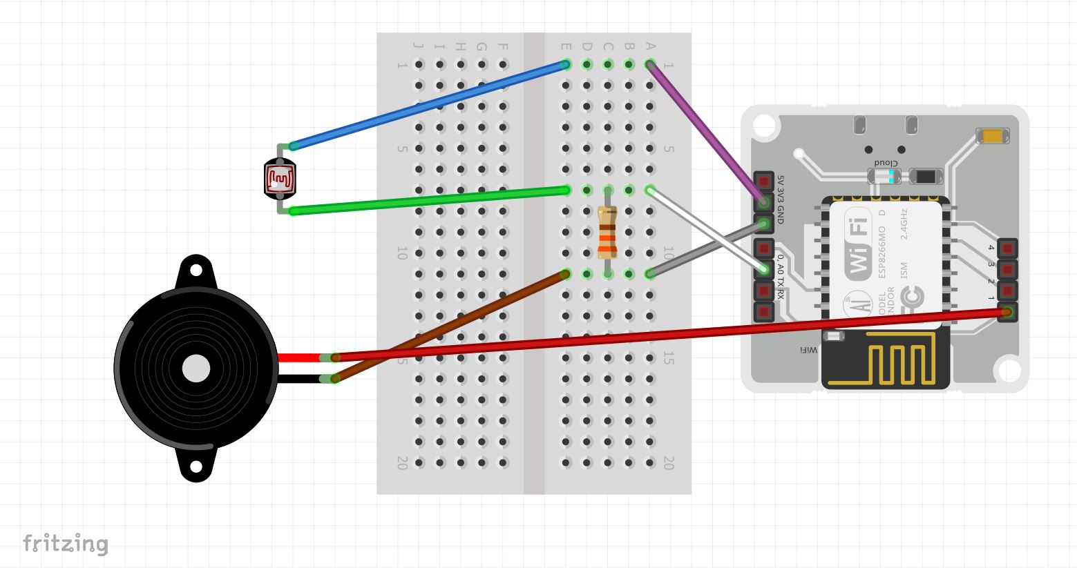
Step 2: Connect the Components (See Circuit Connections after all the Steps)
Step 3: Create a Telegram Bot and Channel -
- Download the Telegram Messaging App and create your account.
- In the Menu, tap on 'New Channel' and add a name to it.
- Make it a 'Public Channel' and write a unique link name and note it down (the part after me./ )
- Now, go back to the normal screen and in the search bar, type in BotFather. Click on the one which has the "Blue Tick symbol"
- Type in the command /newbot, then enter the name, and enter a unique link for the bot.
- The API token will be shown. Note it down and "DO NOT SHARE IT WITH ANYONE".
- Go to the channel just created and make the bot as an Admin of the channel with all the properties (look at last pic).
Step 4: Download VMWare on your laptop and install the Ubuntu.iso file
Step 5: After creating the virtual server, and logging into the server, type the following:
- Update the packages on Ubuntu
sudo apt-get -y update- Install python3 pip3
sudo apt install python3-pip- Installing boltiot library using pip
sudo pip3 install boltiotStep 6: Create the 'config.py' using the command -
sudo nano config.pyStep 7: Enter the code for this document and save it - (see the CODE section)
Step 8: Create the 'burglar_alarm.py' using the command -
sudo nano burglar_alarm.pyStep 9: Enter the code for this document and save it - (see the CODE section)
Step 10: Connect the USB to the Bolt module and switch on the power supply.
Step 11: Connect the Bolt-IoT module to the Bolt-IoT app (either android or ios) by following the steps in the app.
Step 12: Place the laser a certain distance apart but the light should fall directly onto the LDR to work.
Step 13: Enter the following code to start the code on the server and see the magic happen :)
sudo python3 burglar_alarm.pyConnect the components properly and carefully. Double check the connections to prevent short-circuiting and to prevent any damage to the components.
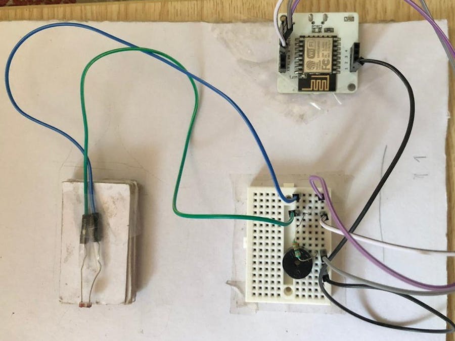
- The LDR (Light-Dependent Resistor) is an input device which measure the amount of the light falling on it. The resistor is connected to the LDR to so that less amount of current flows through it and thus prevents damage.
- The Buzzer (Piezo-Buzzer) is an output device which emits sound.
- The 3v pin of the Bolt-IoT module is connected to one leg of the LDR (via the breadboard) with the purple and blue wire.
- The other end of the LDR is connected to the 330 ohm resistor with the green wire. This is in-turn connected to the "A0" pin of the Bolt module using the white wire.
- The 2nd end of the resistor is connected to ground (on the Bolt module) using the grey wire. The shorter end of the buzzer is also connected in this column.
- The longer end of the buzzer is connected to the '1' pin of the Bolt module using the red wire.
- Thus, the LDR part of the entire circuit is the input, while the Buzzer part is the output.
- The key element of this circuit is the LDR. This is because the resistance of the LDR has an inverse relation with the intensity of light i.e., the resistance of the LDR increases with the decrease in the intensity of light and vice-versa.
- The above circuit is connected to the power supply and the Bolt WIFI Module is connected to the Ubuntu server via the internet. When the laser is switched on, the laser beam falls on the LDR. Since, maximum intensity is received, the resistance of the LDR is minimum. Hence, voltage across it is minimum. This is because of Ohm’s law which states that the voltage across any element in the circuit is directly proportional to the resistance of that element. (V=IR)
- When the laser beam is obstructed, the LDR will receive very low or no light (depending on the amount of obstruction created). Hence, its resistance will increase, which in turn increases the voltage across it. When the voltage across the LDR is above the cut-off voltage of the transistor (in the WIFI module), the transistor is turned on. This makes the current flow to the buzzer, which buzzes for a certain amount of time (here it is about 15 seconds).
- Also, a message will be sent across Telegram stating that the alarm has been activated.
- When the laser beam is restored (the obstruction is removed), the light intensity is increased and in turn the resistance of LDR decreases, hence the voltage across it is below the cut-off voltage of the transistor. Thus, the transistor is turned off. This makes the buzzer stop making noise.
Thus, a successful Laser Security System has been created. It is after the Bolt-IoT training that I could create such a system. This is my First Own Project, I hope you like it. I will try to use Raspberry Pi for the server instead of the laptop. Once I do, I will update it here.
Thank you.


Comments
Please log in or sign up to comment.