The word home automation or Smart Home was coined in 1984 by the American Association of House Builders but it was still just a distant dream back then!, Even though the first remote control toy boat was invented back in 1898 by Nikola Tesla. Then in 1975, the first general-purpose home automation network technology X10 was developed. It is a communication protocol for electronic devices. By 2020 its a whopping US$12.81 billion industry.
The basic control loop for all these devices is very simple as shown below.
Here there will be a sensor converting real-world physical value to an electrical signal such as voltage or current in the case of analog and value in the case of digital and reporting it to a microcomputer called microcontroller which contains a predefined set points which will compare the current sensor reading with setpoint readings and takes the action accordingly.
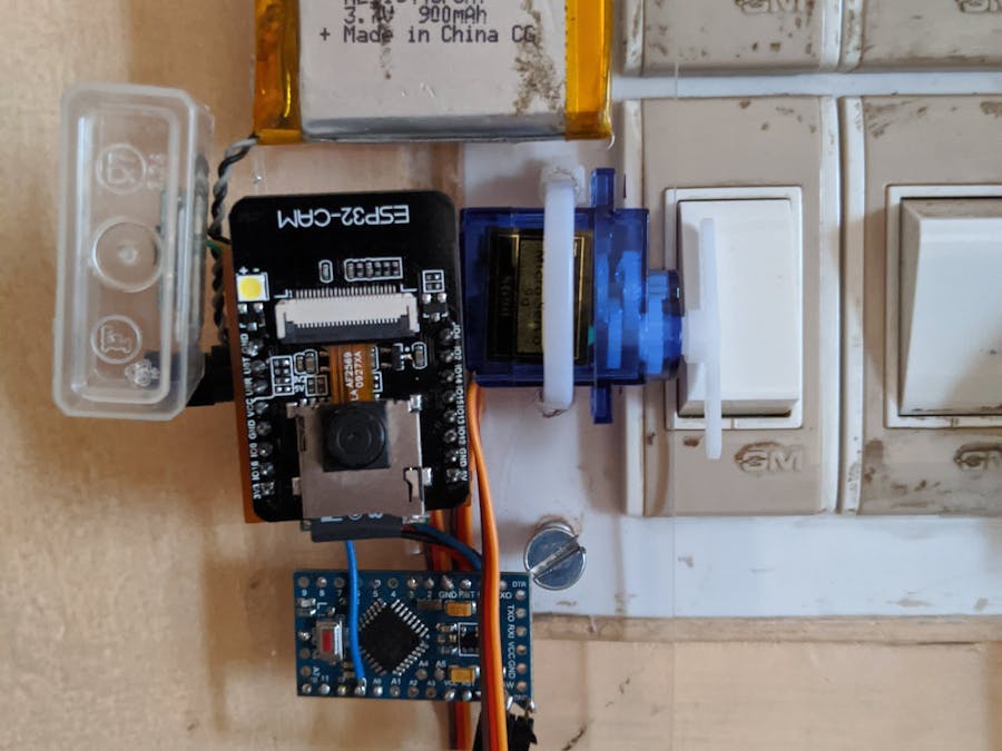
Our goal here is to make a servo motor based automated switch can be retrofitted on to current switchboard. Current home automation solutions are not portable and require professionals to install the wiring and other setups. Here in order to make your home smart no need to replace both switchboard and lights. That's why this solution is important.
In the above picture, total occupancy in the building after work hours may be less than the morning but still, Lights are on all the time. This is a huge waste of energy. By employing small sensor nodes like these pyro sensors, one can save a lot of energy.
Other features include
- 200hrs of battery life,
- Security camera which takes a photo of a person entering the room
- Deep sleep to save battery.
- Portable.
- Sending email alerts
Step 2: Lets test on a breadboard:
In our project sensor is nothing but a small proximity sensor by KEMET SS-430. ( I had applied for the free hardware but my Idea wasn't selected, by looking at the form factor of the sensor I thought it will give better design freedom compared to other proximity sensors so I went ahead and bought one.) The data from the sensor will have a 2 200ms clock pulses as shown in the figure.
In the above figure, the 2 200ms pulses are the ones which show human presence other clock pulses are formed due to false triggering. This false triggering occurring since I was experimenting with the bare sensor without lenses or any other cover. False triggering drastically reduced after I used the plastic enclosure to secure the sensor.
For the test, I just used a microcontroller(Arduino Uno) and the sensor and an LED. After hours of reading sensor values on serial monitor and calibrating it, I came with a small code to correctly detect the presence of a human being in front of it.
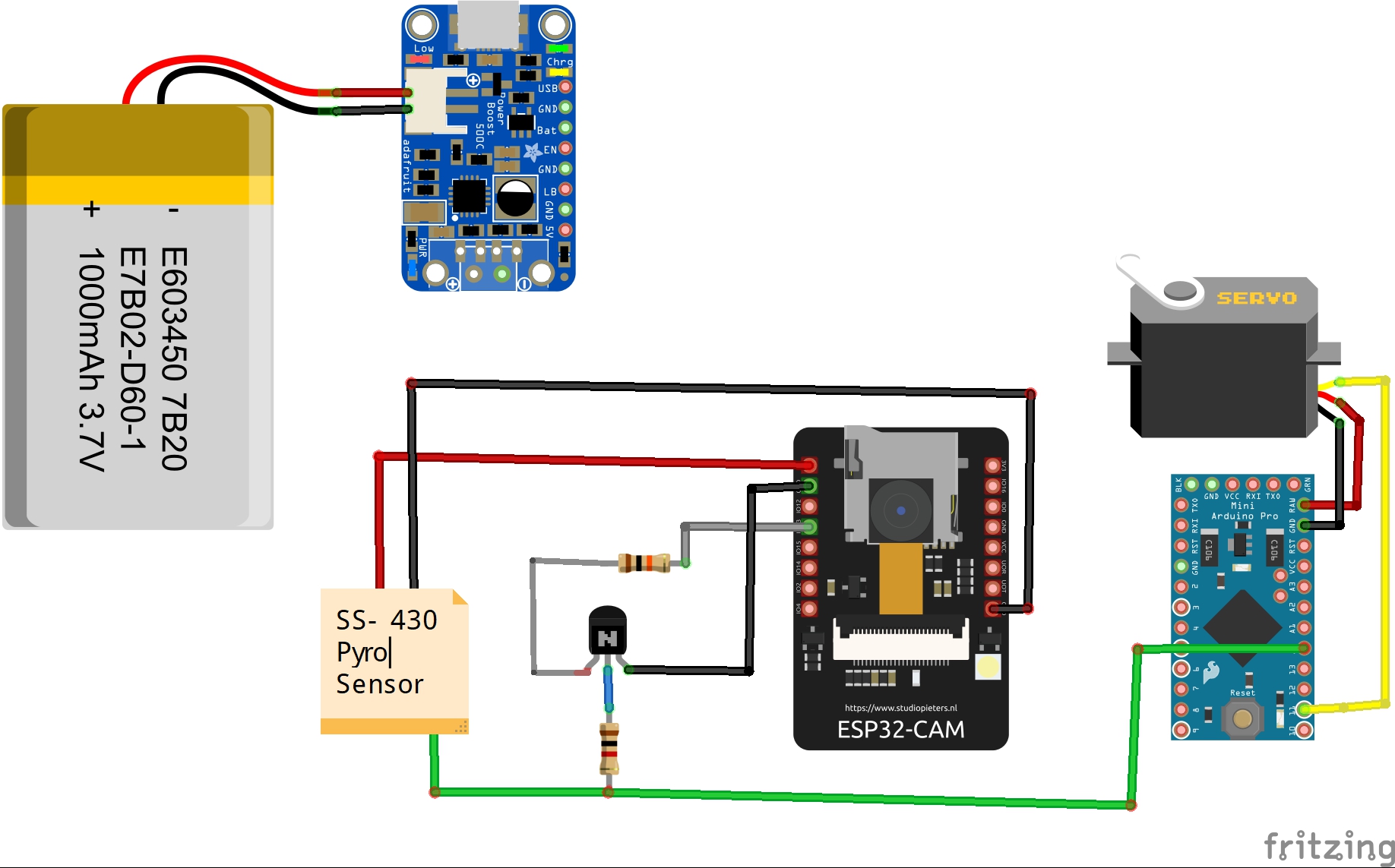
Step 3: Connecting a servo and testing it on ESP32 Camera:With the limited number of pins available on ESP32 Camera, I had to use timer 2 and GPIO2 for driving servo and GPIO13 for wake functionality using the Kemet SS-430 proximity sensor.
Reason for using ESP32 Camera is to take a picture and go to sleep mode when the person enters the room or unauthorised place. The image will be saved in the
SD card. To act immediately on the intruder, the ESP32 will send an email to the preconfigured email ID. This needs ESP32 Mail client Library to be installed. Go to manage Libraries in Arduino IDE and search for the ESP32 Mail client and download. You will need a working email ID whose credentials you need to put in the code and later you will have to enable Less Secure Apps. It's better to create a new Gmail ID for this project.
Step 4 : Testing Proof of conceptFor a simpler exploded view of the project I thought of assembling the things on acrylic sheet in a modular fashion.
There the plastic box for the sensor is helping in reducing the false triggers. Since the ESP camera goes into sleep after taking photos I cannot perform digital signal conditioning operations on the ESP32 camera. Hence I added another microcontroller to reduce the false trigger and signal conditioning and also for driving servo motor.
You can either use esp32 or another microcontroller both works.
The signal from the pyroelectric sensor is fed to the transistor in an open-collector configuration, once the signal comes transistor gets activated as a switch and hence it connects GPIO 13 to the ground and wakes up the ESP32 camera
In code repositories, Pyrolight code along with camera_pins.h is for ESP32 camera rest 2 codes are for testing with Arduino pro mini.
Please find detailed schematics and Kicad PCB in GitHub repository.
Actually I had ordered PCB from china for this project, but I didn't receive it in time because of theCoronavirus outbreak. So I had to use aboost converter and TP4056 module.
Step 5: Mail cameWhen there was an intruder in the vicinity of the sensor, it woke up from the sleep took a picture and sent a mail with an attachment.
Here's how the mail looks like. All this can be done only because of a proximity sensor. Since the whole device is battery powered it allows us to carry anywhere. and make our own smart and safe environment.
You can 3D print an enclosure to fit the electronics as required.
Here's one good design: https://www.thingiverse.com/thing:3816458
Step 6: Working Video :Update: I made a proper PCB shield for esp32 cam board with USB to UART and connectors for servo and the pyro sensor. You can find the Gerber files on my Github repo linked below.
1. Designing a 3D-printed case for the project to make it look like a product
2. Designing a shield for ESP32 CAM [Done !]
3. Improving battery performance
4. Analog signal conditioning circuit instead of a secondary microcontroller.
Finally, I thank hackster.io and Kemet for the opportunity and all the opensource community for taking the time and documenting on the internet.


_3u05Tpwasz.png?auto=compress%2Cformat&w=40&h=40&fit=fillmax&bg=fff&dpr=2)
Comments
Please log in or sign up to comment.