I have been wanting to do this project for a while now. I finally decided to start it and do a few blogs on it.
Back StoryFor many years, I have used and played in Microsoft Flight Simulator X. In anticipation of the upcoming release of the new version - Microsoft Flight Simulator 2020 - I wanted to ensure I had the best set up ready for flight!
My normal set up includes a generic Joystick Controller that I bought when I first got the game many years ago. It does the basic job of flying a plane with X, Y and a single throttle axis that goes up in 25% increments. Recently, I started playing with the F-16 planes in the steam edition of the game. I quickly discovered that 25% increments were way too much power so I started looking at solutions.
You can buy a throttle control kit that has three levers for about $120 AUD from Logitech. You would need two of these to simulate scenarios such has engine failure in bigger aircraft like the Boeing 747 or Airbus A380 (4 engine aircraft) - so about $250 AUD. That would probably have been the easiest solution - but I wanted something that looks a bit more 'authentic'. The authentic looking controllers are about $1000+ AUD.
Then I started to think - why can't I just make one of these using a 3D printer, some sliding potentiometers and a control board? Surely that would be cheaper than $1000?
Introduction - Research & TestingI decided I would use my Robo HAT MM1, slider potentiometer and other basic components to see what could be accomplished.
I knew that CircuitPython had a gamepad software library that makes your CircuitPython code appear like a Joystick. I had an idea that this could be hacked up (easily) and make to suit my purpose. CircuitPython also makes working with hardware easy.
I ended buying some components for a first prototype that included:
- 6 x Sliding Potentiometer from Jaycar
- 4.2k Ohm Resistors
- Heat Shrink
- Colour Coded Wire
So I set off on an adventure to make something cool!
Hardware and CircuitPython TestsThere was a number of small tests I needed to do before going forward due to voltage differences between what the sliders output (0 - 5V) and the signal reading on the Robo HAT MM1 (0 - 3v3).
I attached ONE slider to the Robo HAT to see if I could see the values change. Since the Robo HAT MM1 only has a 5V output power rail and only reads up to 3.3 volt analog signals, there was a mismatch.
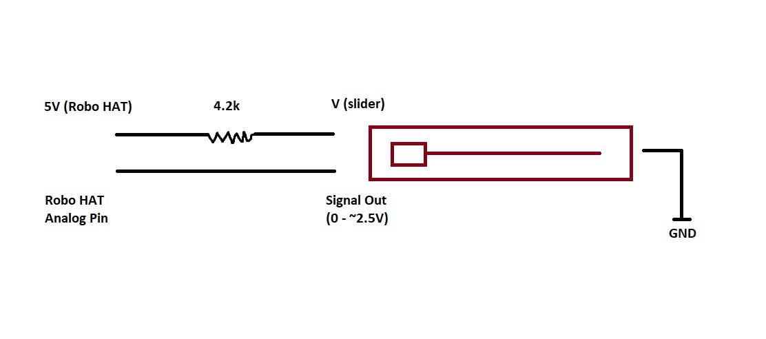
A small circuit was needed to lower the output signal/voltage from the slider pot or change the voltage received by the sliding pot. This was fixed by using a resistor in series with the power from the Robo HAT MM1. This was the code that I used for testing that the signals I was receiving were correct.
import time
import board
import busio
from digitalio import DigitalInOut, Direction
from analogio import AnalogIn
analog_in = AnalogIn(board.RCC1)

def get_voltage(pin):
    return (pin.value * 3.3) / 65536

while True:
    print((get_voltage(analog_in),))
    time.sleep(0.1)
Circuit Diagram(s)
I ended up using the second diagram because it was quicker and easier to solder later on. Both achieve the same goal of dropping the output voltage of the slider potentiometer.
This all worked without too much trouble. I next moved to creating a prototype (it was too hard to test all the sliders at the same time when they are not mounted).
Prototype 1 - Design and HardwareFor the first prototype of this project I used my favourite material to work with: wood.
I measured out some of the distances on a piece of paper and then marked it up on piece of scrap wood that was selected for the project (currently renovating, so wood is plentiful). There was not any logic behind the spacing except that the end slider potentiometer are pointing inwards and needed more space.
After marking it out, it was time to do some drilling to secure the sliders in place. Since this was a prototype, I wasn't really too concerned by the looks. Functionality was more important.
Soldering and WiringThe next step was to crack out the soldering iron and create some wires to link all the sliders together. The plan was to solder the 4.2k resistor in series with the power wire, put on a header/connector and then protect everything with some heat shrink. Straight forward.
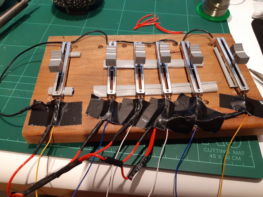
The end result for the first prototype was the below. After soldering the power, ground and signal wires.
It was looking pretty good at this point, I was able to read all six of the sliders at the same time in CircuitPython. However, when I delved a bit deeper, I noticed something odd... the output curve looked really odd with the potentiometers that I had bought.
I took some measurements at set distances (5 mm apart) and graphed it against the voltage that was received on the Robo HAT MM1.
It was no where near what I was expecting. I wanted a nice linear output - not whatever these were doing (which I thought was logarithmic, but it doesn't even seem to be that). If someone knows what kind of output this is - do let me know in the comments.
There was not much I could do with this kind of output, so I decided to purchase some new sliding potentiometers from somewhere else that were 'linear'. The new ones worked like a charm! and I was off again (after adjusting the prototype to fit these new sliders).
New Prototype 1.2You can never go wrong with Gaffa Tape!
I wrote a test CircuitPython program for reading the outputs from all the sliders at the same time. I will leave the link to it here (it's too long to paste).
Next StepsThe next step of this project is to try and make CircuitPython HID library work with this customised control column setup. I have taken some steps already and done some preliminary tests.
I also asked DanH on the Adafruit Discord about it and he provided some background information and very helpful hints around the USB HID library. There is a bit of work involved that I'll save for the next blog post.
There is also a 3D model prototype that has been created for this project, which I'll share soon.
Then finally testing in Microsoft Flight Simulator X and Microsoft Flight Simulator 2020!
More to come.


Comments
Please log in or sign up to comment.