Introduction:
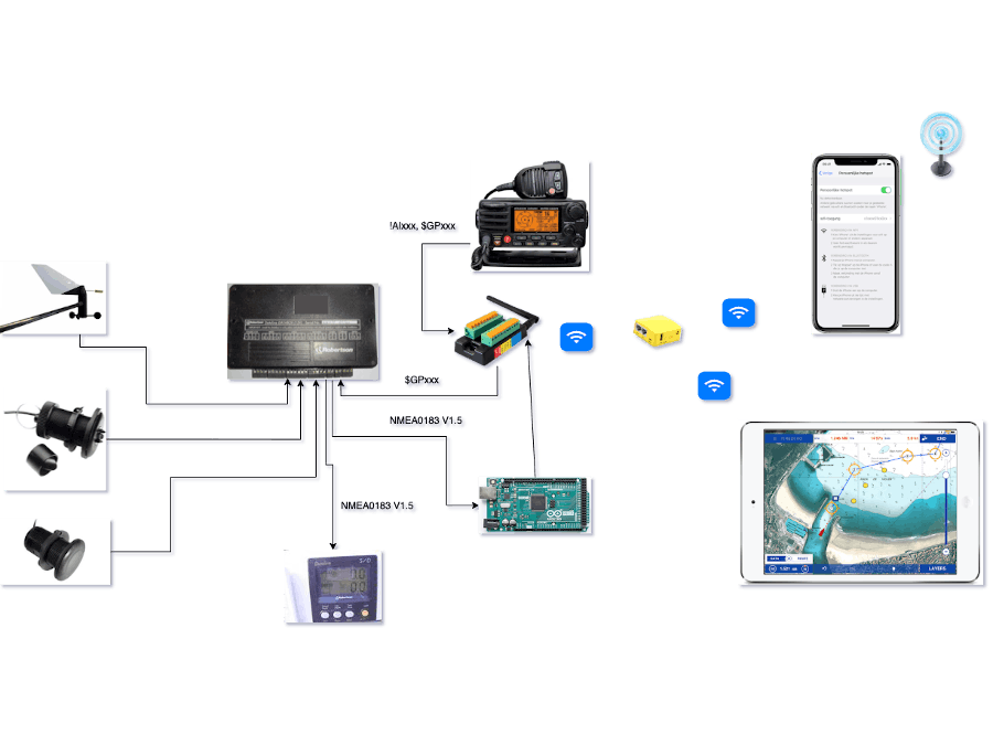
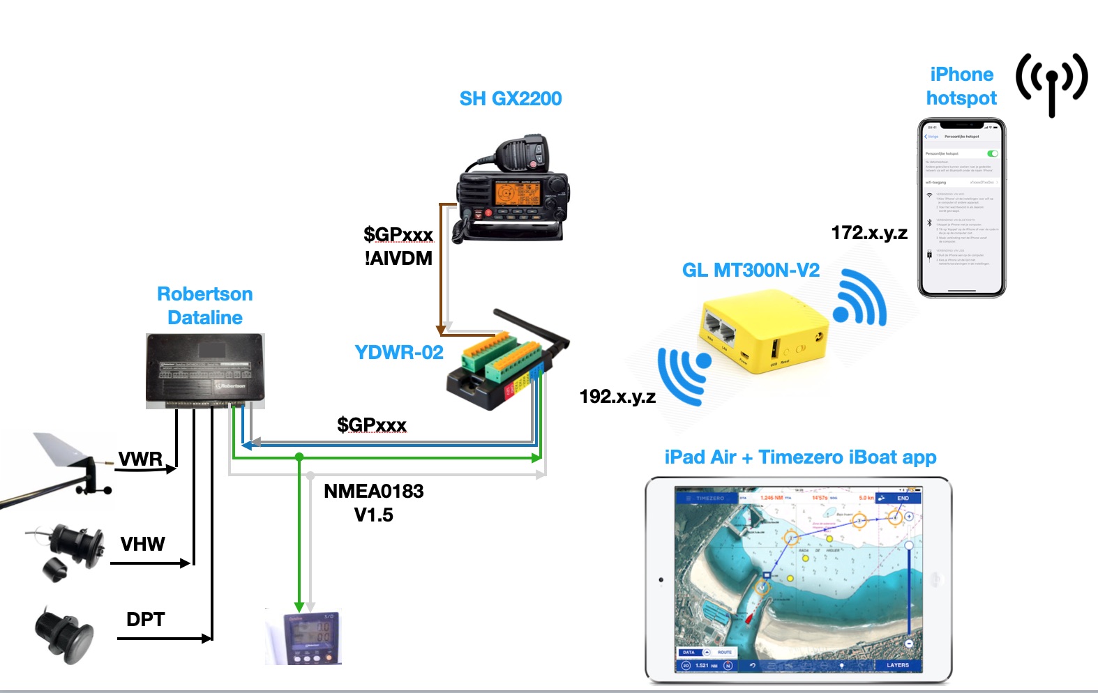
I've an old Robertson data network on board feeding the on board devices with NMEA0183 v1.5. Not only is this RS-232 related, but the NMEA sentences are not terminated with a checksum. Most navigation apps don't care and checksum checking can be overridden by the user. There is how ever a newer NMEA0183 v2.0 related data stream for GPS and AIS information that needs to be integrated with the old data stream, better known as multiplexing.
Fig. 1: Current situation on board
I initially went for the easy way out and burned some Euro's on a commercial multiplexer, which is a great product from YachtDevices; the YDWR02 (4 NMEA inputs and 4 NMEA outputs). It even offers the option to pass through the old V1.5 NMEA0183 data. Unfortunately with this option activated the data can not be filtered out and that is where the problem, well the inconvenience, started. Multiplexing the the 2 data steams results in a frozen HDG at 2 degrees in the navigation app on the iPad. Since this is a given fact, I need to work on the other end of the wire and manipulate the old NMEA0183 data before it is send to the iPad. Fortunately there is a workaround and I can use the equipment, but without the old data stream resulting in only GPS and AIS info ( or all data with a frozen HDG at 2 degrees North)
Since I don't have a sensor or valid data available telling the magnetic or true heading I decided to integrate an MPU-9250 - GY9250 unit; a 9 DOF thingy with a digital compass, accelerometer and gyroscope.
All this also gives me the opportunity to design a user interface for all the incoming data like a Multi Function Display. Hence the 3, 5" TFT touchscreen.
The Arduino multiplexer project on King Tide Sailing triggered me and here I am. Never soldered a pin on a PCB before and yet there are a lot of them waiting to be soldered like a pro.
The plan:Well there are several options:
- the easy way out: read the NMEA0183 data stream from the Robertson Databox into the Arduino. Filter the data that I 'm interested in, add a checksum if necessary (GPS and AIS data contain a checksum). Extend the data with the data coming from the MPU 9250 unit and pass it through to the multiplexer ( adding the AIS data) which sends it via WiFi to the iPad. And create some nice gauges to show on the TFT display. Meaning several grouped pages with related data and a datalogger for the NMEA data. Or even trend data for the average speed and wind etc...
- the hard way: sell the YDWR02 and do all the multiplexing via the Arduino and add WiFi capabilities to it so it can act as a client in my boat network.
Either way I'll follow the MoSCoW principle; Must, Should, Could and Would haves. Manipulating the original NMEA0183 v1.5 data stream is must a have. Integrating the 9 DoF thingy is a Should have and adding the TFT display features is a Could have. The replacement of the current multiplexer by the Arduino is a Would or Wish to have for now.
Since I've a strong OO-background and the Arduino is merely sequential or loop based I'm looking into a project from Kevin Gagnon (based on a project from Alan Burlison) to implement an event driven architecture as much as possible into this project.
Status:Currently I'm waiting for all the ordered items to arrive; ETA is end of May.
As per Apr 30st, 2020 the pin headers and the 9 DoF thingy have been delivered.May 1, 2020; soldering tin has been delivered
May 6, 2020: The PCB solder buddy and RS-422/485 to TTL converter have been delivered
Intermediate challenge:From the old Robertson Databox there are 5 wires available for communication; Red (+ 12V) Brown (Rx), White (Tx), Green (Gnd) and Black (-0V).
This looks suspiciously like the RS-232 wiring as used in NMEA0183 in the past. Voltages range between + 12V and -12V for reps. 0 and 1. I have always used it like this in the network and it has always worked like this without any problems.
However…. the Arduino works with voltage between 0 and 3.3 or 5 V (you can choose) and 12V makes a toast of my Arduino and the UART is TTL based.
This problem can be solved by adding an RS-232 <-> TTL converter, but then you have to make sure that you really have RS-232. Because the newer version of NMEA0183 works with RS-422 and the voltage is between 0 and 5 V (formally even between 0 and 10V). So I took a voltmeter to measure the wires and see the voltage fluctuate between 0 and 3.5V. So no negative voltages, which in itself would mean that it is based on RS-422 protocol.
So I ordered a multimeter with an oscilloscope(see here for extensive review) function to measure and analyze the signal and then determine whether I need an RS-232 <-> TTL converter or an RS-422.485 <-> TTL converter….
May 7, 2020, Yeahhh the Mega has arrived including " Die inoffizielle Anleitung zum Arduino!" and the board is working. Still waiting for the Buck step down converter to drive the Arduino with 7V (coming from 12V), the solder station, the RS-232 <-> TTL converter and the 810 pcs component kit
May 9, 2020. The de-soldering thread and the Buck step down converter has arrived.
While waiting on the deliveries I've started building the wire-frame for the application.
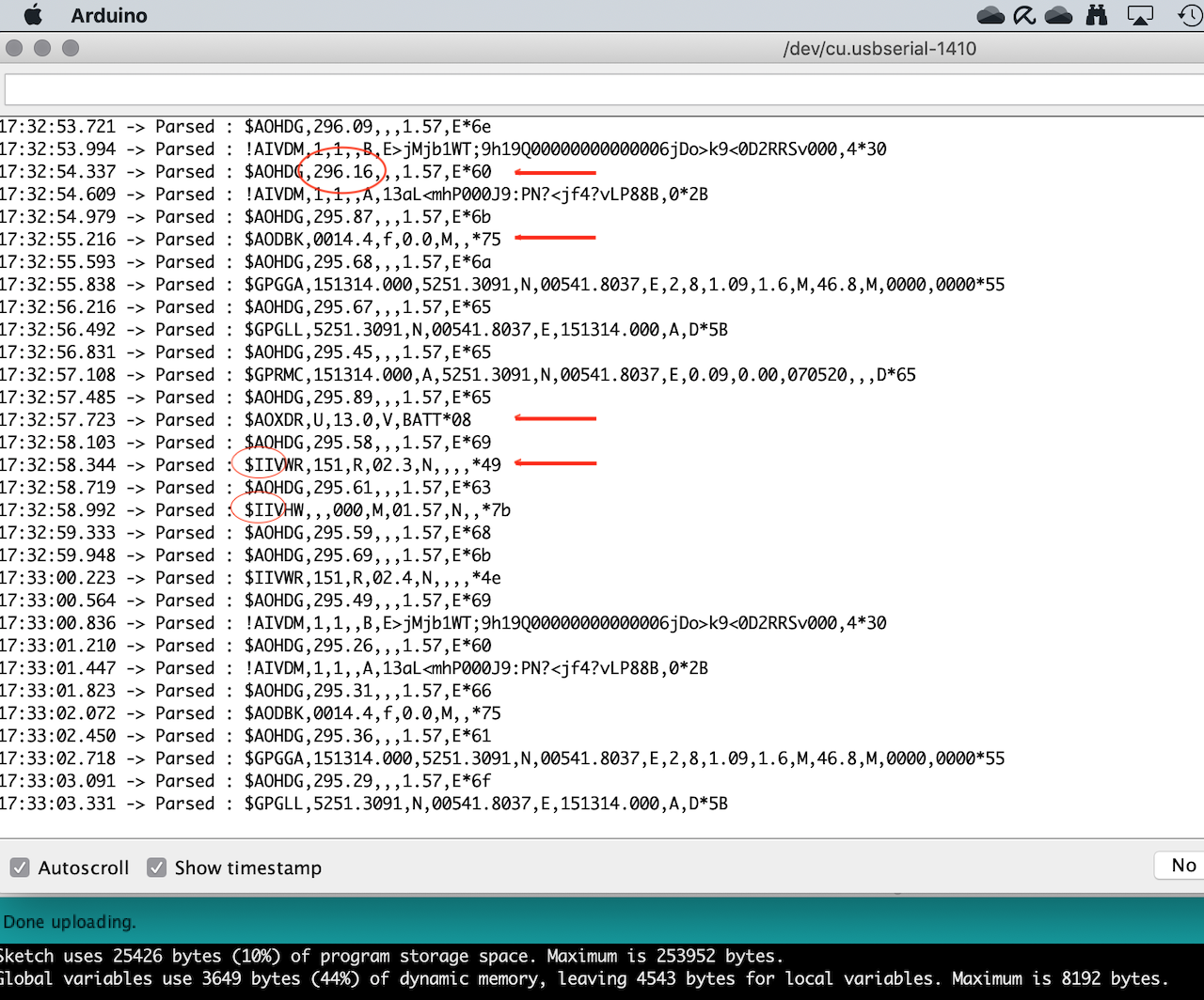
May 10, 2020. The NMEA parser (the NMEAtor) is working fine. The code contains some testsoftware (that can be disabled by out-commenting #define TEST) that can send NMEA-sentences. I've selected 10 sentences from my log to test against.
May 11, 2020. The multimeter with oscilloscope view has been delivered and I jumped into the boat to do some measurements on the NMEA signal. Based on what I saw I came to the conclusion that the signal is between 0V and 3, 1V and that I'll use the RS 422/ 485 <-> TTL converter.
May 13, 2020. The header pins have arrived. And I started soldering the pins to the MPU9250 board with a gas heated soldering iron
Progress:
My first attempt to write object oriented software managed by a task scheduler resulted in a good design, but in lack of variable memory to store the variables. Limited space and an OO design is not a happy marriage. So I had to overhaul my design and I've the first version running, reading the MPU9250 heading filtered for tilt and pitch. And the old NMEA0183 V1.5 sentences with out checksum or invalid format have been successfully parsed...
May 17, 2020. During testing with the MPU I noticed that I got 0x73 back from the Who_AM_I call instead of the expected 0x71. The code works with a slight adjustment on the IF statement. But wondering why this happened I found datasheet for the MPU9255, which will give back the 0x73 value. The good news is that the library works without complaining. There are some rumours that the chips contains a bug in the calibration values as discussed on the blog of Sureshjoshi https://sureshjoshi.com/embedded/invensense-imus-what-to-know/. Need to dive into that...
May 18, 2020. The 830 pcs wiring kit has arrived; lots of leds, wires, resistors, capacitors, potentiometer, a 4n35, a 74HC595. Still waiting for the soldering iron, the RS232<->TTlL converters and the TFT display...
May 29, 2020. The RS-232<->TTL converters have arrived.
May 20, 2020. The 3, 5" TFT touchscreen has arrived.
May 22, 2020. Finally all parts are complete. In the meanwhile I've been working on the software to get the display working. So at this point I can start soldering the bits and pieces together and connect the prototype to the NMEA talker.
Well at least important to note is that I've switched the Arduino IDE for the Visual Studio Code with the PlatformIO plugin installed. So from now on the files will be .cpp files instead of .ino files.
Intermediate result:May 23, 2020. The software is ready to get tested on board. The hardware needs to be soldered and then the whole prototype can be tested in a preliminary test. Whoohoo!
Progress:
Unfortunately the pre-FAT failed big time. Although I'd tested the principle of the the pieces of code, putting them to work in real life was a total different experience. A frustrating one at least.
The NMEA signal from the network couldn't be read from te port and neither did the signal coming from the output port breath some life in my network. I took me sometime to understand what I was doing wrong. And there were several....
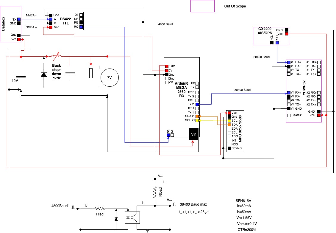
One issue had to due with the inverting of the signal by the RS422<->TTL converter. I'm now using a digital pin (53) via Softwareserial, acting as a UART and inverting the signal.
As this being my first Arduino project, I had not fully understand how the Arduino communication is implemented. In short it a character by character principle. I also had made some quirky mind fucks resulting in bad code.
With the current version I can read NMEA data and display the data on screen of the TFT display. I'm using an NMEA Simulator that can send several NMEA sentences by WiFi or by RS-232 cable. At a certain point the communication stalls, but the Arduino is still working. Restarting the simulator fixes the problem. So I guess it's not my code causing the stall. Next thing to test is the communication with the network from the Arduino via Serial port 2.
2nd FAT has been successful on board. Lessens learned; you cannot simultaneously read and write to different Softwareserial ports on different baud rates. So the software now reads on 4800Bd from Rx2 en writes on 38400 Bd to port 50 via SoftwareSerial. The first important milestone has been accomplished.
UPDATE July 10th, 2020: Calibrating the MPU in combination with the Arduino MEGA2560 R3 was a pain in the butt. No stable calibration values and according no reliable compass readings. Following a thread by Kris Winer, I concluded that the MEGA2560 is not fit for duty and a faster chipset is required, or another MPU.
So I took an important decision the out-comment all the MPU code (still available in the source though) and leave it as a Wish to Have for now.
So the next step is build my own project box , the enclosure for the board and display as for the TS-422/485<->TTL converter I used. I got inspired by The Ben Heck Show
And my first box for the Buck converter is a fact. I learned a lot by doing so and the project box for the Arduino will be almost perfect :-).
Once the box is ready I can assemble the project on board!
ClosureFinally the three boxes, one for the Buck converter, the RS422<->TTL Converter, and for the Arduino are ready and the system is installed on board.
So this is version 1.0 of the NMEAtor. As from know I'll start optimizing the system based on the experience. For now this project has come to an end :-)
Heart transplant
In practice, it turned out that every now and then a message got corrupted in the NMEAtor. Analysis shows that the LCD screen causes such a delay in the process. The LCD screen is a “dumb” display; without its own CPU and RAM and each pixel has to be supplied by the Arduino and that takes time; too much time for 100% reliable operation.
Since I have noticed that the ESP-32 is so much more powerful than the Arduino Mega2560 and I have 2 more, I decided to build an ESP version of the NMEAtor. The software can be found here. In addition, I have an intelligent Nextion 3.5 ″ display from the first phase of the Wind display. Together this is a powerful combination that can easily handle the tasks. Again I use an RS-232 <-> TTL converter to supply the signals from the network up to 3.3V to the ESP via 1 of the 3 UARTS of the ESP. A 2nd UART is used to control the display at TTL level. Finally, use a Software serial port to present the data at RS-232 level at 38,400 Bd to the multiplexer.
The kitchen table test (FAT) went well. Now there is still a test on board with the real network to be done (SAT). Then the ESP must be built in a box together with the RS-232 <-> TTL converter and then it can be installed on board. I still have enough material, so I will manually make such a box.


_wzec989qrF.jpg?auto=compress%2Cformat&w=48&h=48&fit=fill&bg=ffffff)


Comments
Please log in or sign up to comment.