

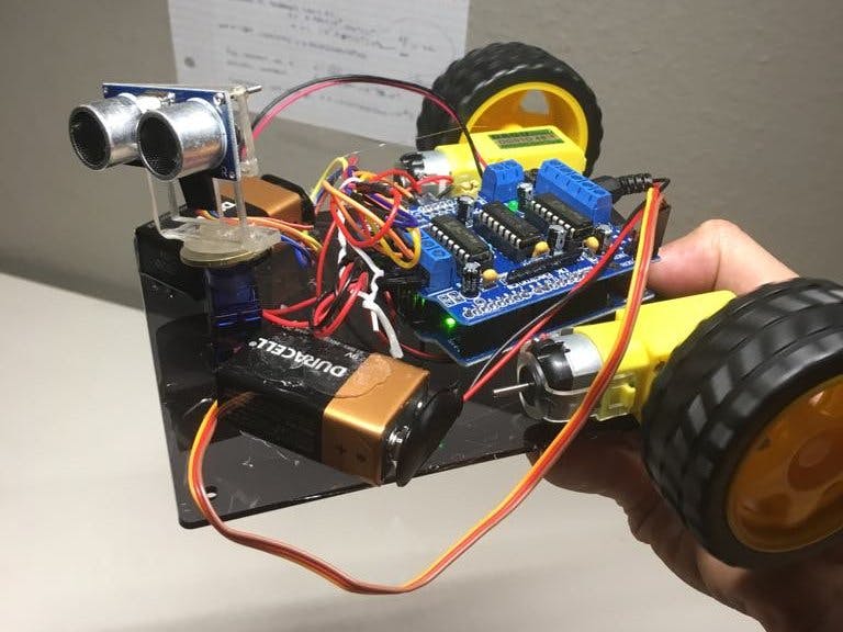
Hardware components | ||||||
_ztBMuBhMHo.jpg?auto=compress%2Cformat&w=48&h=48&fit=fill&bg=ffffff) |
| × | 1 | |||
 |
| × | 1 | |||
 |
| × | 1 | |||
 |
| × | 1 | |||
 |
| × | 1 | |||
NOTE: Although the project is stated to take 5 hours, it may take significantly longer, depending on whether you decide to use the source code or NOT. The libraries provided are for your use to understanding how you may call the functions to control the:
DC Motors, TowerPro servo, or Ultrasonic sensors.
Here is a video of my project being tested out:
So, this is my very first project involving electronic hardware. I decided to try a project that had information regarding its parts and assembly readily available in a video (i.e. YouTube) so that I could follow. (Tutorial Video BELOW)
I have prior experience learning C, C++ and Java languages. For Arduino, all that is required is knowledge on C, using loops, functions, and utilizing certain methods (functions) provided by the libraries in the video tutorial given here:
Uploader: Mert Arduino & Tech
The parts I purchased were not directly from the link provided by the video uploader, but rather were sourced myself from other websites or hardware shops.
To acquire the parts for building this robot, you may follow the links to the parts from the YouTube video above, or my own personal sources which I will list later below.
The source code below provided to upload into the Arduino-Uno micro-controller is from User: Mert Arduino & Tech but I have annotated it as well for future reference or newcomer's to understand the purpose of each line of code.
main.cpp (Annotated with notes explaining robot's loop execution)
Arduino#include <AFMotor.h>
#include <Servo.h>
#include <NewPing.h>
#define TRIG_PIN A4
#define ECHO_PIN A5
#define MAX_DISTANCE_POSSIBLE 1000
#define MAX_SPEED 150 //
#define MOTORS_CALIBRATION_OFFSET 3
#define COLL_DIST 20 //the object is 20cm away from the sensor, this is defined to be the collision distance
#define TURN_DIST COLL_DIST+10 //we need to give the vehicle some allowance infront of it so that it may turn without bumping into obstacles. The distance of safe turn is 30cm away from obstacle
NewPing sonar(TRIG_PIN, ECHO_PIN, MAX_DISTANCE_POSSIBLE);
AF_DCMotor leftMotor(4, MOTOR12_8KHZ);
AF_DCMotor rightMotor(3, MOTOR12_8KHZ);
Servo neckControllerServoMotor;
int pos = 0; //NOTE THAT POS = 0 MEANS EYES LOOKING STRAIGHT RIGHT
int maxDist = 0;
int maxAngle = 0;
int maxRight = 0;
int maxLeft = 0;
int maxFront = 0;
int course = 0;
int curDist = 0;
String motorSet = "";
int speedSet = 0;
void setup() {
neckControllerServoMotor.attach(10);
neckControllerServoMotor.write(90); //sets the "eyes" to looking straight ahead
delay(2000);
checkPath();
motorSet = "FORWARD";
neckControllerServoMotor.write(90);
moveForward();
}
void loop() {
checkForward();
checkPath();
}
void checkPath() {
int curLeft = 0;
int curFront = 0;
int curRight = 0;
int curDist = 0;
neckControllerServoMotor.write(144); //sets viewing angle to sweep from R to L, starting at 144 deg (i.e. looking at the LEFT)
delay(120); //THE FUNCTION MAKES ANGLE DECREMENT 8 TIMES, EACH OF 18 DEGREES. i.e. Looking from R to L at 18 degree sweeps
for(pos = 144; pos >= 36; pos-=18)
{
neckControllerServoMotor.write(pos);
delay(90); //DELAY ALLOWS VEHICLE TO WAIT FOR "EYES" TO TURN BEFORE MOVING OFF
checkForward(); //STARTS OFF MOVING FORWARD
curDist = readPing(); //ASSIGNS curDist the distance in centimeters of the object ahead
if (curDist < COLL_DIST) { //this if condition, where curDist < collision dist will only be required on instances where the robot has just started
checkCourse(); //OR WHILE IT IS SWEEPING, ENCOUNTERS ANOTHER OBJECT WHERE curDist is STILL LESS THAN COLLISION DISTANCE. checkCourse() will reverse and then head in another direction.
break; //when it sweeps L to R in this 18 degree interval, it will reverse and call setCourse which causes it to turn in the direction away from the obstacle
}
//this occurs until curDist is NOT less than collision dist, the break will break out of the loop, re-run the curDist < COLL_DIST function again and backup/reverse
//until curDist >= COLL_DIST
if (curDist < TURN_DIST) { //TURN_DIST proximity will always be maintained from the "eyes"
changePath(); //when TURN_DIST breached, vehicle will change path. NOTE THAT BOTH WHEELS STILL MOVING FORWARD. changePath will cause the OTHER WHEEL TO MOVE IN OPPOSITE DIRECTION
} //THEREBY CAUSING THE VEHICLE TO ROTATE AWAY FROM OBSTACLE. THEN IN 0.4s, THE SAME WHEEL MOVES FORWARD AGAIN SO THAT VEHICLE RESUMES STRAIGHT PATH OF MOVEMENT
if (curDist > curDist) {maxAngle = pos;}
if (pos > 90 && curDist > curLeft) { curLeft = curDist;} //WE ARE UPDATING DISTANCES LEFT FRONT AND RIGHT
if (pos == 90 && curDist > curFront) {curFront = curDist;} //IF LOOKING eg. LEFTWARDS AND CURRENT DISTANCE GREATER THAN curLeft VARIABLE, THEN REASSIGN (I.E. UPDATE curLeft)
if (pos < 90 && curDist > curRight) {curRight = curDist;} //UPDATE curFront and curRight as well when gazing at any of these directions
}
maxLeft = curLeft; //THESE ARE NEW MAX DISTANCES FROM THE LEFT FRONT AND RIGHT
maxRight = curRight;
maxFront = curFront;
}
void setCourse() {
if (maxAngle < 90) {turnRight();}
if (maxAngle > 90) {turnLeft();}
maxLeft = 0;
maxRight = 0;
maxFront = 0;
}
void checkCourse() {
moveBackward();
delay(500);
moveStop();
setCourse();
}
void changePath() {
if (pos < 90) {lookLeft();}
if (pos > 90) {lookRight();}
}
int readPing() {
delay(70);
unsigned int uS = sonar.ping(); //activating the sonar, it emits Ultrasound at 40kHz (Spd of Sound = 340 m/s or 0.0034cm/uS (microsecond))
int cm = uS/US_ROUNDTRIP_CM; //uS is asigned a value by the .ping function, which returns the time taken for soundwave to reach object and return to it
return cm; //we take that time and divide it by the time taken per centimeter in order to get 2xdistance, in cm, of object away from Ultrasonic sensor
} //ping returns distance of object (in centimeters) from ultrasonic sensor
void checkForward() { if (motorSet=="FORWARD") {leftMotor.run(FORWARD); rightMotor.run(FORWARD); } }
void checkBackward() { if (motorSet=="BACKWARD") {leftMotor.run(BACKWARD); rightMotor.run(BACKWARD); } }
void moveStop() {leftMotor.run(RELEASE); rightMotor.run(RELEASE);}
void moveForward() {
motorSet = "FORWARD";
leftMotor.run(FORWARD);
rightMotor.run(FORWARD);
for (speedSet = 0; speedSet < MAX_SPEED; speedSet +=2)
{
leftMotor.setSpeed(speedSet+MOTORS_CALIBRATION_OFFSET);
rightMotor.setSpeed(speedSet);
delay(5);
}
}
void moveBackward() {
motorSet = "BACKWARD";
leftMotor.run(BACKWARD);
rightMotor.run(BACKWARD);
for (speedSet = 0; speedSet < MAX_SPEED; speedSet +=2)
{
leftMotor.setSpeed(speedSet+MOTORS_CALIBRATION_OFFSET);
rightMotor.setSpeed(speedSet);
delay(5);
}
}
void turnRight() { //TURNING FUNCTION COMPRISES OF SUBSEQUENTLY MOVING FORWARD (BOTH L & R)
motorSet = "RIGHT";
leftMotor.run(FORWARD);
rightMotor.run(BACKWARD);
delay(400);
motorSet = "FORWARD";
leftMotor.run(FORWARD);
rightMotor.run(FORWARD);
}
void turnLeft() {
motorSet = "LEFT";
leftMotor.run(BACKWARD);
rightMotor.run(FORWARD);
delay(400);
motorSet = "FORWARD";
leftMotor.run(FORWARD);
rightMotor.run(FORWARD);
}
void lookRight() {rightMotor.run(BACKWARD); delay(400); rightMotor.run(FORWARD);}
void lookLeft() {leftMotor.run(BACKWARD); delay(400); leftMotor.run(FORWARD);}
// Adafruit Motor shield library
// copyright Adafruit Industries LLC, 2009
// this code is public domain, enjoy!


#if (ARDUINO >= 100)
  #include "Arduino.h"
#else
  #if defined(__AVR__)
    #include <avr/io.h>
  #endif
  #include "WProgram.h"
#endif

#include "AFMotor.h"


static uint8_t latch_state;

#if (MICROSTEPS == 8)
uint8_t microstepcurve[] = {0, 50, 98, 142, 180, 212, 236, 250, 255};
#elif (MICROSTEPS == 16)
uint8_t microstepcurve[] = {0, 25, 50, 74, 98, 120, 141, 162, 180, 197, 212, 225, 236, 244, 250, 253, 255};
#endif

AFMotorController::AFMotorController(void) {
    TimerInitalized = false;
}

void AFMotorController::enable(void) {
  // setup the latch
  /*
  LATCH_DDR |= _BV(LATCH);
  ENABLE_DDR |= _BV(ENABLE);
  CLK_DDR |= _BV(CLK);
  SER_DDR |= _BV(SER);
  */
  pinMode(MOTORLATCH, OUTPUT);
  pinMode(MOTORENABLE, OUTPUT);
  pinMode(MOTORDATA, OUTPUT);
  pinMode(MOTORCLK, OUTPUT);

  latch_state = 0;

  latch_tx();  // "reset"

  //ENABLE_PORT &= ~_BV(ENABLE); // enable the chip outputs!
  digitalWrite(MOTORENABLE, LOW);
}


void AFMotorController::latch_tx(void) {
  uint8_t i;

  //LATCH_PORT &= ~_BV(LATCH);
  digitalWrite(MOTORLATCH, LOW);

  //SER_PORT &= ~_BV(SER);
  digitalWrite(MOTORDATA, LOW);

  for (i=0; i<8; i++) {
    //CLK_PORT &= ~_BV(CLK);
    digitalWrite(MOTORCLK, LOW);

    if (latch_state & _BV(7-i)) {
      //SER_PORT |= _BV(SER);
      digitalWrite(MOTORDATA, HIGH);
    } else {
      //SER_PORT &= ~_BV(SER);
      digitalWrite(MOTORDATA, LOW);
    }
    //CLK_PORT |= _BV(CLK);
    digitalWrite(MOTORCLK, HIGH);
  }
  //LATCH_PORT |= _BV(LATCH);
  digitalWrite(MOTORLATCH, HIGH);
}

static AFMotorController MC;

/******************************************
               MOTORS
******************************************/
inline void initPWM1(uint8_t freq) {
#if defined(__AVR_ATmega8__) || \
    defined(__AVR_ATmega48__) || \
    defined(__AVR_ATmega88__) || \
    defined(__AVR_ATmega168__) || \
    defined(__AVR_ATmega328P__)
    // use PWM from timer2A on PB3 (Arduino pin #11)
    TCCR2A |= _BV(COM2A1) | _BV(WGM20) | _BV(WGM21); // fast PWM, turn on oc2a
    TCCR2B = freq & 0x7;
    OCR2A = 0;
#elif defined(__AVR_ATmega1280__) || defined(__AVR_ATmega2560__)
    // on arduino mega, pin 11 is now PB5 (OC1A)
    TCCR1A |= _BV(COM1A1) | _BV(WGM10); // fast PWM, turn on oc1a
    TCCR1B = (freq & 0x7) | _BV(WGM12);
    OCR1A = 0;
#elif defined(__PIC32MX__)
    #if defined(PIC32_USE_PIN9_FOR_M1_PWM)
        // Make sure that pin 11 is an input, since we have tied together 9 and 11
        pinMode(9, OUTPUT);
        pinMode(11, INPUT);
        if (!MC.TimerInitalized)
        {   // Set up Timer2 for 80MHz counting fro 0 to 256
            T2CON = 0x8000 | ((freq & 0x07) << 4); // ON=1, FRZ=0, SIDL=0, TGATE=0, TCKPS=<freq>, T32=0, TCS=0; // ON=1, FRZ=0, SIDL=0, TGATE=0, TCKPS=0, T32=0, TCS=0
            TMR2 = 0x0000;
            PR2 = 0x0100;
            MC.TimerInitalized = true;
        }
         // Setup OC4 (pin 9) in PWM mode, with Timer2 as timebase
        OC4CON = 0x8006;    // OC32 = 0, OCTSEL=0, OCM=6
        OC4RS = 0x0000;
        OC4R = 0x0000;
    #elif defined(PIC32_USE_PIN10_FOR_M1_PWM)
        // Make sure that pin 11 is an input, since we have tied together 9 and 11
        pinMode(10, OUTPUT);
        pinMode(11, INPUT);
        if (!MC.TimerInitalized)
        {   // Set up Timer2 for 80MHz counting fro 0 to 256
            T2CON = 0x8000 | ((freq & 0x07) << 4); // ON=1, FRZ=0, SIDL=0, TGATE=0, TCKPS=<freq>, T32=0, TCS=0; // ON=1, FRZ=0, SIDL=0, TGATE=0, TCKPS=0, T32=0, TCS=0
            TMR2 = 0x0000;
            PR2 = 0x0100;
            MC.TimerInitalized = true;
        }
         // Setup OC5 (pin 10) in PWM mode, with Timer2 as timebase
        OC5CON = 0x8006;    // OC32 = 0, OCTSEL=0, OCM=6
        OC5RS = 0x0000;
        OC5R = 0x0000;
    #else
        // If we are not using PWM for pin 11, then just do digital
        digitalWrite(11, LOW);
    #endif
#else
   #error "This chip is not supported!"
#endif
    #if !defined(PIC32_USE_PIN9_FOR_M1_PWM) && !defined(PIC32_USE_PIN10_FOR_M1_PWM)
        pinMode(11, OUTPUT);
    #endif
}

inline void setPWM1(uint8_t s) {
#if defined(__AVR_ATmega8__) || \
    defined(__AVR_ATmega48__) || \
    defined(__AVR_ATmega88__) || \
    defined(__AVR_ATmega168__) || \
    defined(__AVR_ATmega328P__)
    // use PWM from timer2A on PB3 (Arduino pin #11)
    OCR2A = s;
#elif defined(__AVR_ATmega1280__) || defined(__AVR_ATmega2560__)
    // on arduino mega, pin 11 is now PB5 (OC1A)
    OCR1A = s;
#elif defined(__PIC32MX__)
    #if defined(PIC32_USE_PIN9_FOR_M1_PWM)
        // Set the OC4 (pin 9) PMW duty cycle from 0 to 255
        OC4RS = s;
    #elif defined(PIC32_USE_PIN10_FOR_M1_PWM)
        // Set the OC5 (pin 10) PMW duty cycle from 0 to 255
        OC5RS = s;
    #else
        // If we are not doing PWM output for M1, then just use on/off
        if (s > 127)
        {
            digitalWrite(11, HIGH);
        }
        else
        {
            digitalWrite(11, LOW);
        }
    #endif
#else
   #error "This chip is not supported!"
#endif
}

inline void initPWM2(uint8_t freq) {
#if defined(__AVR_ATmega8__) || \
    defined(__AVR_ATmega48__) || \
    defined(__AVR_ATmega88__) || \
    defined(__AVR_ATmega168__) || \
    defined(__AVR_ATmega328P__)
    // use PWM from timer2B (pin 3)
    TCCR2A |= _BV(COM2B1) | _BV(WGM20) | _BV(WGM21); // fast PWM, turn on oc2b
    TCCR2B = freq & 0x7;
    OCR2B = 0;
#elif defined(__AVR_ATmega1280__) || defined(__AVR_ATmega2560__)
    // on arduino mega, pin 3 is now PE5 (OC3C)
    TCCR3A |= _BV(COM1C1) | _BV(WGM10); // fast PWM, turn on oc3c
    TCCR3B = (freq & 0x7) | _BV(WGM12);
    OCR3C = 0;
#elif defined(__PIC32MX__)
    if (!MC.TimerInitalized)
    {   // Set up Timer2 for 80MHz counting fro 0 to 256
        T2CON = 0x8000 | ((freq & 0x07) << 4); // ON=1, FRZ=0, SIDL=0, TGATE=0, TCKPS=<freq>, T32=0, TCS=0; // ON=1, FRZ=0, SIDL=0, TGATE=0, TCKPS=0, T32=0, TCS=0
        TMR2 = 0x0000;
        PR2 = 0x0100;
        MC.TimerInitalized = true;
    }
    // Setup OC1 (pin3) in PWM mode, with Timer2 as timebase
    OC1CON = 0x8006;    // OC32 = 0, OCTSEL=0, OCM=6
    OC1RS = 0x0000;
    OC1R = 0x0000;
#else
   #error "This chip is not supported!"
#endif

    pinMode(3, OUTPUT);
}

inline void setPWM2(uint8_t s) {
#if defined(__AVR_ATmega8__) || \
    defined(__AVR_ATmega48__) || \
    defined(__AVR_ATmega88__) || \
    defined(__AVR_ATmega168__) || \
    defined(__AVR_ATmega328P__)
    // use PWM from timer2A on PB3 (Arduino pin #11)
    OCR2B = s;
#elif defined(__AVR_ATmega1280__) || defined(__AVR_ATmega2560__)
    // on arduino mega, pin 11 is now PB5 (OC1A)
    OCR3C = s;
#elif defined(__PIC32MX__)
    // Set the OC1 (pin3) PMW duty cycle from 0 to 255
    OC1RS = s;
#else
   #error "This chip is not supported!"
#endif
}

inline void initPWM3(uint8_t freq) {
#if defined(__AVR_ATmega8__) || \
    defined(__AVR_ATmega48__) || \
    defined(__AVR_ATmega88__) || \
    defined(__AVR_ATmega168__) || \
    defined(__AVR_ATmega328P__)
    // use PWM from timer0A / PD6 (pin 6)
    TCCR0A |= _BV(COM0A1) | _BV(WGM00) | _BV(WGM01); // fast PWM, turn on OC0A
    //TCCR0B = freq & 0x7;
    OCR0A = 0;
#elif defined(__AVR_ATmega1280__) || defined(__AVR_ATmega2560__)
    // on arduino mega, pin 6 is now PH3 (OC4A)
    TCCR4A |= _BV(COM1A1) | _BV(WGM10); // fast PWM, turn on oc4a
    TCCR4B = (freq & 0x7) | _BV(WGM12);
    //TCCR4B = 1 | _BV(WGM12);
    OCR4A = 0;
#elif defined(__PIC32MX__)
    if (!MC.TimerInitalized)
    {   // Set up Timer2 for 80MHz counting fro 0 to 256
        T2CON = 0x8000 | ((freq & 0x07) << 4); // ON=1, FRZ=0, SIDL=0, TGATE=0, TCKPS=<freq>, T32=0, TCS=0; // ON=1, FRZ=0, SIDL=0, TGATE=0, TCKPS=0, T32=0, TCS=0
        TMR2 = 0x0000;
        PR2 = 0x0100;
        MC.TimerInitalized = true;
    }
    // Setup OC3 (pin 6) in PWM mode, with Timer2 as timebase
    OC3CON = 0x8006;    // OC32 = 0, OCTSEL=0, OCM=6
    OC3RS = 0x0000;
    OC3R = 0x0000;
#else
   #error "This chip is not supported!"
#endif
    pinMode(6, OUTPUT);
}

inline void setPWM3(uint8_t s) {
#if defined(__AVR_ATmega8__) || \
    defined(__AVR_ATmega48__) || \
    defined(__AVR_ATmega88__) || \
    defined(__AVR_ATmega168__) || \
    defined(__AVR_ATmega328P__)
    // use PWM from timer0A on PB3 (Arduino pin #6)
    OCR0A = s;
#elif defined(__AVR_ATmega1280__) || defined(__AVR_ATmega2560__)
    // on arduino mega, pin 6 is now PH3 (OC4A)
    OCR4A = s;
#elif defined(__PIC32MX__)
    // Set the OC3 (pin 6) PMW duty cycle from 0 to 255
    OC3RS = s;
#else
   #error "This chip is not supported!"
#endif
}


inline void initPWM4(uint8_t freq) {
#if defined(__AVR_ATmega8__) || \
    defined(__AVR_ATmega48__) || \
    defined(__AVR_ATmega88__) || \
    defined(__AVR_ATmega168__) || \
    defined(__AVR_ATmega328P__)
    // use PWM from timer0B / PD5 (pin 5)
    TCCR0A |= _BV(COM0B1) | _BV(WGM00) | _BV(WGM01); // fast PWM, turn on oc0a
    //TCCR0B = freq & 0x7;
    OCR0B = 0;
#elif defined(__AVR_ATmega1280__) || defined(__AVR_ATmega2560__)
    // on arduino mega, pin 5 is now PE3 (OC3A)
    TCCR3A |= _BV(COM1A1) | _BV(WGM10); // fast PWM, turn on oc3a
    TCCR3B = (freq & 0x7) | _BV(WGM12);
    //TCCR4B = 1 | _BV(WGM12);
    OCR3A = 0;
#elif defined(__PIC32MX__)
    if (!MC.TimerInitalized)
    {   // Set up Timer2 for 80MHz counting fro 0 to 256
        T2CON = 0x8000 | ((freq & 0x07) << 4); // ON=1, FRZ=0, SIDL=0, TGATE=0, TCKPS=<freq>, T32=0, TCS=0; // ON=1, FRZ=0, SIDL=0, TGATE=0, TCKPS=0, T32=0, TCS=0
        TMR2 = 0x0000;
        PR2 = 0x0100;
        MC.TimerInitalized = true;
    }
    // Setup OC2 (pin 5) in PWM mode, with Timer2 as timebase
    OC2CON = 0x8006;    // OC32 = 0, OCTSEL=0, OCM=6
    OC2RS = 0x0000;
    OC2R = 0x0000;
#else
   #error "This chip is not supported!"
#endif
    pinMode(5, OUTPUT);
}

inline void setPWM4(uint8_t s) {
#if defined(__AVR_ATmega8__) || \
    defined(__AVR_ATmega48__) || \
    defined(__AVR_ATmega88__) || \
    defined(__AVR_ATmega168__) || \
    defined(__AVR_ATmega328P__)
    // use PWM from timer0A on PB3 (Arduino pin #6)
    OCR0B = s;
#elif defined(__AVR_ATmega1280__) || defined(__AVR_ATmega2560__)
    // on arduino mega, pin 6 is now PH3 (OC4A)
    OCR3A = s;
#elif defined(__PIC32MX__)
    // Set the OC2 (pin 5) PMW duty cycle from 0 to 255
    OC2RS = s;
#else
   #error "This chip is not supported!"
#endif
}

AF_DCMotor::AF_DCMotor(uint8_t num, uint8_t freq) {
  motornum = num;
  pwmfreq = freq;

  MC.enable();

  switch (num) {
  case 1:
    latch_state &= ~_BV(MOTOR1_A) & ~_BV(MOTOR1_B); // set both motor pins to 0
    MC.latch_tx();
    initPWM1(freq);
    break;
  case 2:
    latch_state &= ~_BV(MOTOR2_A) & ~_BV(MOTOR2_B); // set both motor pins to 0
    MC.latch_tx();
    initPWM2(freq);
    break;
  case 3:
    latch_state &= ~_BV(MOTOR3_A) & ~_BV(MOTOR3_B); // set both motor pins to 0
    MC.latch_tx();
    initPWM3(freq);
    break;
  case 4:
    latch_state &= ~_BV(MOTOR4_A) & ~_BV(MOTOR4_B); // set both motor pins to 0
    MC.latch_tx();
    initPWM4(freq);
    break;
  }
}

void AF_DCMotor::run(uint8_t cmd) {
  uint8_t a, b;
  switch (motornum) {
  case 1:
    a = MOTOR1_A; b = MOTOR1_B; break;
  case 2:
    a = MOTOR2_A; b = MOTOR2_B; break;
  case 3:
    a = MOTOR3_A; b = MOTOR3_B; break;
  case 4:
    a = MOTOR4_A; b = MOTOR4_B; break;
  default:
    return;
  }

  switch (cmd) {
  case FORWARD:
    latch_state |= _BV(a);
    latch_state &= ~_BV(b);
    MC.latch_tx();
    break;
  case BACKWARD:
    latch_state &= ~_BV(a);
    latch_state |= _BV(b);
    MC.latch_tx();
    break;
  case RELEASE:
    latch_state &= ~_BV(a);     // A and B both low
    latch_state &= ~_BV(b);
    MC.latch_tx();
    break;
  }
}

void AF_DCMotor::setSpeed(uint8_t speed) {
  switch (motornum) {
  case 1:
    setPWM1(speed); break;
  case 2:
    setPWM2(speed); break;
  case 3:
    setPWM3(speed); break;
  case 4:
    setPWM4(speed); break;
  }
}

/******************************************
               STEPPERS
******************************************/

AF_Stepper::AF_Stepper(uint16_t steps, uint8_t num) {
  MC.enable();

  revsteps = steps;
  steppernum = num;
  currentstep = 0;

  if (steppernum == 1) {
    latch_state &= ~_BV(MOTOR1_A) & ~_BV(MOTOR1_B) &
      ~_BV(MOTOR2_A) & ~_BV(MOTOR2_B); // all motor pins to 0
    MC.latch_tx();

    // enable both H bridges
    pinMode(11, OUTPUT);
    pinMode(3, OUTPUT);
    digitalWrite(11, HIGH);
    digitalWrite(3, HIGH);

    // use PWM for microstepping support
    initPWM1(STEPPER1_PWM_RATE);
    initPWM2(STEPPER1_PWM_RATE);
    setPWM1(255);
    setPWM2(255);

  } else if (steppernum == 2) {
    latch_state &= ~_BV(MOTOR3_A) & ~_BV(MOTOR3_B) &
      ~_BV(MOTOR4_A) & ~_BV(MOTOR4_B); // all motor pins to 0
    MC.latch_tx();

    // enable both H bridges
    pinMode(5, OUTPUT);
    pinMode(6, OUTPUT);
    digitalWrite(5, HIGH);
    digitalWrite(6, HIGH);

    // use PWM for microstepping support
    // use PWM for microstepping support
    initPWM3(STEPPER2_PWM_RATE);
    initPWM4(STEPPER2_PWM_RATE);
    setPWM3(255);
    setPWM4(255);
  }
}

void AF_Stepper::setSpeed(uint16_t rpm) {
  usperstep = 60000000 / ((uint32_t)revsteps * (uint32_t)rpm);
  steppingcounter = 0;
}

void AF_Stepper::release(void) {
  if (steppernum == 1) {
    latch_state &= ~_BV(MOTOR1_A) & ~_BV(MOTOR1_B) &
      ~_BV(MOTOR2_A) & ~_BV(MOTOR2_B); // all motor pins to 0
    MC.latch_tx();
  } else if (steppernum == 2) {
    latch_state &= ~_BV(MOTOR3_A) & ~_BV(MOTOR3_B) &
      ~_BV(MOTOR4_A) & ~_BV(MOTOR4_B); // all motor pins to 0
    MC.latch_tx();
  }
}

void AF_Stepper::step(uint16_t steps, uint8_t dir,  uint8_t style) {
  uint32_t uspers = usperstep;
  uint8_t ret = 0;

  if (style == INTERLEAVE) {
    uspers /= 2;
  }
 else if (style == MICROSTEP) {
    uspers /= MICROSTEPS;
    steps *= MICROSTEPS;
#ifdef MOTORDEBUG
    Serial.print("steps = "); Serial.println(steps, DEC);
#endif
  }

  while (steps--) {
    ret = onestep(dir, style);
    delay(uspers/1000); // in ms
    steppingcounter += (uspers % 1000);
    if (steppingcounter >= 1000) {
      delay(1);
      steppingcounter -= 1000;
    }
  }
  if (style == MICROSTEP) {
    while ((ret != 0) && (ret != MICROSTEPS)) {
      ret = onestep(dir, style);
      delay(uspers/1000); // in ms
      steppingcounter += (uspers % 1000);
      if (steppingcounter >= 1000) {
	delay(1);
	steppingcounter -= 1000;
      }
    }
  }
}

uint8_t AF_Stepper::onestep(uint8_t dir, uint8_t style) {
  uint8_t a, b, c, d;
  uint8_t ocrb, ocra;

  ocra = ocrb = 255;

  if (steppernum == 1) {
    a = _BV(MOTOR1_A);
    b = _BV(MOTOR2_A);
    c = _BV(MOTOR1_B);
    d = _BV(MOTOR2_B);
  } else if (steppernum == 2) {
    a = _BV(MOTOR3_A);
    b = _BV(MOTOR4_A);
    c = _BV(MOTOR3_B);
    d = _BV(MOTOR4_B);
  } else {
    return 0;
  }

  // next determine what sort of stepping procedure we're up to
  if (style == SINGLE) {
    if ((currentstep/(MICROSTEPS/2)) % 2) { // we're at an odd step, weird
      if (dir == FORWARD) {
	currentstep += MICROSTEPS/2;
      }
      else {
	currentstep -= MICROSTEPS/2;
      }
    } else {           // go to the next even step
      if (dir == FORWARD) {
	currentstep += MICROSTEPS;
      }
      else {
	currentstep -= MICROSTEPS;
      }
    }
  } else if (style == DOUBLE) {
    if (! (currentstep/(MICROSTEPS/2) % 2)) { // we're at an even step, weird
      if (dir == FORWARD) {
	currentstep += MICROSTEPS/2;
      } else {
	currentstep -= MICROSTEPS/2;
      }
    } else {           // go to the next odd step
      if (dir == FORWARD) {
	currentstep += MICROSTEPS;
      } else {
	currentstep -= MICROSTEPS;
      }
    }
  } else if (style == INTERLEAVE) {
    if (dir == FORWARD) {
       currentstep += MICROSTEPS/2;
    } else {
       currentstep -= MICROSTEPS/2;
    }
  }

  if (style == MICROSTEP) {
    if (dir == FORWARD) {
      currentstep++;
    } else {
      // BACKWARDS
      currentstep--;
    }

    currentstep += MICROSTEPS*4;
    currentstep %= MICROSTEPS*4;

    ocra = ocrb = 0;
    if ( (currentstep >= 0) && (currentstep < MICROSTEPS)) {
      ocra = microstepcurve[MICROSTEPS - currentstep];
      ocrb = microstepcurve[currentstep];
    } else if  ( (currentstep >= MICROSTEPS) && (currentstep < MICROSTEPS*2)) {
      ocra = microstepcurve[currentstep - MICROSTEPS];
      ocrb = microstepcurve[MICROSTEPS*2 - currentstep];
    } else if  ( (currentstep >= MICROSTEPS*2) && (currentstep < MICROSTEPS*3)) {
      ocra = microstepcurve[MICROSTEPS*3 - currentstep];
      ocrb = microstepcurve[currentstep - MICROSTEPS*2];
    } else if  ( (currentstep >= MICROSTEPS*3) && (currentstep < MICROSTEPS*4)) {
      ocra = microstepcurve[currentstep - MICROSTEPS*3];
      ocrb = microstepcurve[MICROSTEPS*4 - currentstep];
    }
  }

  currentstep += MICROSTEPS*4;
  currentstep %= MICROSTEPS*4;

#ifdef MOTORDEBUG
  Serial.print("current step: "); Serial.println(currentstep, DEC);
  Serial.print(" pwmA = "); Serial.print(ocra, DEC);
  Serial.print(" pwmB = "); Serial.println(ocrb, DEC);
#endif

  if (steppernum == 1) {
    setPWM1(ocra);
    setPWM2(ocrb);
  } else if (steppernum == 2) {
    setPWM3(ocra);
    setPWM4(ocrb);
  }


  // release all
  latch_state &= ~a & ~b & ~c & ~d; // all motor pins to 0

  //Serial.println(step, DEC);
  if (style == MICROSTEP) {
    if ((currentstep >= 0) && (currentstep < MICROSTEPS))
      latch_state |= a | b;
    if ((currentstep >= MICROSTEPS) && (currentstep < MICROSTEPS*2))
      latch_state |= b | c;
    if ((currentstep >= MICROSTEPS*2) && (currentstep < MICROSTEPS*3))
      latch_state |= c | d;
    if ((currentstep >= MICROSTEPS*3) && (currentstep < MICROSTEPS*4))
      latch_state |= d | a;
  } else {
    switch (currentstep/(MICROSTEPS/2)) {
    case 0:
      latch_state |= a; // energize coil 1 only
      break;
    case 1:
      latch_state |= a | b; // energize coil 1+2
      break;
    case 2:
      latch_state |= b; // energize coil 2 only
      break;
    case 3:
      latch_state |= b | c; // energize coil 2+3
      break;
    case 4:
      latch_state |= c; // energize coil 3 only
      break;
    case 5:
      latch_state |= c | d; // energize coil 3+4
      break;
    case 6:
      latch_state |= d; // energize coil 4 only
      break;
    case 7:
      latch_state |= d | a; // energize coil 1+4
      break;
    }
  }


  MC.latch_tx();
  return currentstep;
}
// Adafruit Motor shield library
// copyright Adafruit Industries LLC, 2009
// this code is public domain, enjoy!

/*
 * Usage Notes:
 * For PIC32, all features work properly with the following two exceptions:
 *
 * 1) Because the PIC32 only has 5 PWM outputs, and the AFMotor shield needs 6
 *    to completely operate (four for motor outputs and two for RC servos), the
 *    M1 motor output will not have PWM ability when used with a PIC32 board.
 *    However, there is a very simple workaround. If you need to drive a stepper
 *    or DC motor with PWM on motor output M1, you can use the PWM output on pin
 *    9 or pin 10 (normally use for RC servo outputs on Arduino, not needed for
 *    RC servo outputs on PIC32) to drive the PWM input for M1 by simply putting
 *    a jumber from pin 9 to pin 11 or pin 10 to pin 11. Then uncomment one of the
 *    two #defines below to activate the PWM on either pin 9 or pin 10. You will
 *    then have a fully functional microstepping for 2 stepper motors, or four
 *    DC motor outputs with PWM.
 *
 * 2) There is a conflict between RC Servo outputs on pins 9 and pins 10 and
 *    the operation of DC motors and stepper motors as of 9/2012. This issue
 *    will get fixed in future MPIDE releases, but at the present time it means
 *    that the Motor Party example will NOT work properly. Any time you attach
 *    an RC servo to pins 9 or pins 10, ALL PWM outputs on the whole board will
 *    stop working. Thus no steppers or DC motors.
 *
 */
// <BPS> 09/15/2012 Modified for use with chipKIT boards


#ifndef _AFMotor_h_
#define _AFMotor_h_

#include <inttypes.h>
#if defined(__AVR__)
    #include <avr/io.h>

    //#define MOTORDEBUG 1

    #define MICROSTEPS 16                       // 8 or 16

    #define MOTOR12_64KHZ _BV(CS20)             // no prescale
    #define MOTOR12_8KHZ _BV(CS21)              // divide by 8
    #define MOTOR12_2KHZ _BV(CS21) | _BV(CS20)  // divide by 32
    #define MOTOR12_1KHZ _BV(CS22)              // divide by 64

    #define MOTOR34_64KHZ _BV(CS00)             // no prescale
    #define MOTOR34_8KHZ _BV(CS01)              // divide by 8
    #define MOTOR34_1KHZ _BV(CS01) | _BV(CS00)  // divide by 64

    #define DC_MOTOR_PWM_RATE   MOTOR34_8KHZ    // PWM rate for DC motors
    #define STEPPER1_PWM_RATE   MOTOR12_64KHZ   // PWM rate for stepper 1
    #define STEPPER2_PWM_RATE   MOTOR34_64KHZ   // PWM rate for stepper 2

#elif defined(__PIC32MX__)
    //#define MOTORDEBUG 1

    // Uncomment the one of following lines if you have put a jumper from
    // either pin 9 to pin 11 or pin 10 to pin 11 on your Motor Shield.
    // Either will enable PWM for M1
    //#define PIC32_USE_PIN9_FOR_M1_PWM
    //#define PIC32_USE_PIN10_FOR_M1_PWM

    #define MICROSTEPS 16       // 8 or 16

    // For PIC32 Timers, define prescale settings by PWM frequency
    #define MOTOR12_312KHZ  0   // 1:1, actual frequency 312KHz
    #define MOTOR12_156KHZ  1   // 1:2, actual frequency 156KHz
    #define MOTOR12_64KHZ   2   // 1:4, actual frequency 78KHz
    #define MOTOR12_39KHZ   3   // 1:8, acutal frequency 39KHz
    #define MOTOR12_19KHZ   4   // 1:16, actual frequency 19KHz
    #define MOTOR12_8KHZ    5   // 1:32, actual frequency 9.7KHz
    #define MOTOR12_4_8KHZ  6   // 1:64, actual frequency 4.8KHz
    #define MOTOR12_2KHZ    7   // 1:256, actual frequency 1.2KHz
    #define MOTOR12_1KHZ    7   // 1:256, actual frequency 1.2KHz

    #define MOTOR34_312KHZ  0   // 1:1, actual frequency 312KHz
    #define MOTOR34_156KHZ  1   // 1:2, actual frequency 156KHz
    #define MOTOR34_64KHZ   2   // 1:4, actual frequency 78KHz
    #define MOTOR34_39KHZ   3   // 1:8, acutal frequency 39KHz
    #define MOTOR34_19KHZ   4   // 1:16, actual frequency 19KHz
    #define MOTOR34_8KHZ    5   // 1:32, actual frequency 9.7KHz
    #define MOTOR34_4_8KHZ  6   // 1:64, actual frequency 4.8KHz
    #define MOTOR34_2KHZ    7   // 1:256, actual frequency 1.2KHz
    #define MOTOR34_1KHZ    7   // 1:256, actual frequency 1.2KHz

    // PWM rate for DC motors.
    #define DC_MOTOR_PWM_RATE   MOTOR34_39KHZ
    // Note: for PIC32, both of these must be set to the same value
    // since there's only one timebase for all 4 PWM outputs
    #define STEPPER1_PWM_RATE   MOTOR12_39KHZ
    #define STEPPER2_PWM_RATE   MOTOR34_39KHZ

#endif

// Bit positions in the 74HCT595 shift register output
#define MOTOR1_A 2
#define MOTOR1_B 3
#define MOTOR2_A 1
#define MOTOR2_B 4
#define MOTOR4_A 0
#define MOTOR4_B 6
#define MOTOR3_A 5
#define MOTOR3_B 7

// Constants that the user passes in to the motor calls
#define FORWARD 1
#define BACKWARD 2
#define BRAKE 3
#define RELEASE 4

// Constants that the user passes in to the stepper calls
#define SINGLE 1
#define DOUBLE 2
#define INTERLEAVE 3
#define MICROSTEP 4

/*
#define LATCH 4
#define LATCH_DDR DDRB
#define LATCH_PORT PORTB

#define CLK_PORT PORTD
#define CLK_DDR DDRD
#define CLK 4

#define ENABLE_PORT PORTD
#define ENABLE_DDR DDRD
#define ENABLE 7

#define SER 0
#define SER_DDR DDRB
#define SER_PORT PORTB
*/

// Arduino pin names for interface to 74HCT595 latch
#define MOTORLATCH 12
#define MOTORCLK 4
#define MOTORENABLE 7
#define MOTORDATA 8

class AFMotorController
{
  public:
    AFMotorController(void);
    void enable(void);
    friend class AF_DCMotor;
    void latch_tx(void);
    uint8_t TimerInitalized;
};

class AF_DCMotor
{
 public:
  AF_DCMotor(uint8_t motornum, uint8_t freq = DC_MOTOR_PWM_RATE);
  void run(uint8_t);
  void setSpeed(uint8_t);

 private:
  uint8_t motornum, pwmfreq;
};

class AF_Stepper {
 public:
  AF_Stepper(uint16_t, uint8_t);
  void step(uint16_t steps, uint8_t dir,  uint8_t style = SINGLE);
  void setSpeed(uint16_t);
  uint8_t onestep(uint8_t dir, uint8_t style);
  void release(void);
  uint16_t revsteps; // # steps per revolution
  uint8_t steppernum;
  uint32_t usperstep, steppingcounter;
 private:
  uint8_t currentstep;

};

uint8_t getlatchstate(void);

#endif
// ---------------------------------------------------------------------------
// NewPing Library - v1.8 - 07/30/2016
//
// AUTHOR/LICENSE:
// Created by Tim Eckel - teckel@leethost.com
// Copyright 2016 License: GNU GPL v3 http://www.gnu.org/licenses/gpl.html
//
// LINKS:
// Project home: https://bitbucket.org/teckel12/arduino-new-ping/wiki/Home
// Blog: http://arduino.cc/forum/index.php/topic,106043.0.html
//
// DISCLAIMER:
// This software is furnished "as is", without technical support, and with no
// warranty, express or implied, as to its usefulness for any purpose.
//
// BACKGROUND:
// When I first received an ultrasonic sensor I was not happy with how poorly
// it worked. Quickly I realized the problem wasn't the sensor, it was the
// available ping and ultrasonic libraries causing the problem. The NewPing
// library totally fixes these problems, adds many new features, and breaths
// new life into these very affordable distance sensors.
//
// FEATURES:
// * Works with many different ultrasonic sensors: SR04, SRF05, SRF06, DYP-ME007, URM37 & Parallax PING))).
// * Compatible with the entire Arduino line-up (and clones), Teensy family (including $19 96Mhz 32 bit Teensy 3.2) and non-AVR microcontrollers.
// * Interface with all but the SRF06 sensor using only one Arduino pin.
// * Doesn't lag for a full second if no ping/echo is received.
// * Ping sensors consistently and reliably at up to 30 times per second.
// * Timer interrupt method for event-driven sketches.
// * Built-in digital filter method ping_median() for easy error correction.
// * Uses port registers for a faster pin interface and smaller code size.
// * Allows you to set a maximum distance where pings beyond that distance are read as no ping "clear".
// * Ease of using multiple sensors (example sketch with 15 sensors).
// * More accurate distance calculation (cm, inches & uS).
// * Doesn't use pulseIn, which is slow and gives incorrect results with some ultrasonic sensor models.
// * Actively developed with features being added and bugs/issues addressed.
//
// CONSTRUCTOR:
//   NewPing sonar(trigger_pin, echo_pin [, max_cm_distance])
//     trigger_pin & echo_pin - Arduino pins connected to sensor trigger and echo.
//       NOTE: To use the same Arduino pin for trigger and echo, specify the same pin for both values.
//     max_cm_distance - [Optional] Maximum distance you wish to sense. Default=500cm.
//
// METHODS:
//   sonar.ping([max_cm_distance]) - Send a ping and get the echo time (in microseconds) as a result. [max_cm_distance] allows you to optionally set a new max distance.
//   sonar.ping_in([max_cm_distance]) - Send a ping and get the distance in whole inches. [max_cm_distance] allows you to optionally set a new max distance.
//   sonar.ping_cm([max_cm_distance]) - Send a ping and get the distance in whole centimeters. [max_cm_distance] allows you to optionally set a new max distance.
//   sonar.ping_median(iterations [, max_cm_distance]) - Do multiple pings (default=5), discard out of range pings and return median in microseconds. [max_cm_distance] allows you to optionally set a new max distance.
//   NewPing::convert_in(echoTime) - Convert echoTime from microseconds to inches (rounds to nearest inch).
//   NewPing::convert_cm(echoTime) - Convert echoTime from microseconds to centimeters (rounds to nearest cm).
//   sonar.ping_timer(function [, max_cm_distance]) - Send a ping and call function to test if ping is complete. [max_cm_distance] allows you to optionally set a new max distance.
//   sonar.check_timer() - Check if ping has returned within the set distance limit.
//   NewPing::timer_us(frequency, function) - Call function every frequency microseconds.
//   NewPing::timer_ms(frequency, function) - Call function every frequency milliseconds.
//   NewPing::timer_stop() - Stop the timer.
//
// HISTORY:
// 07/30/2016 v1.8 - Added support for non-AVR microcontrollers. For non-AVR
//   microcontrollers, advanced ping_timer() timer methods are disabled due to
//   inconsistencies or no support at all between platforms. However, standard
//   ping methods are all supported. Added new optional variable to ping(),
//   ping_in(), ping_cm(), ping_median(), and ping_timer() methods which allows
//   you to set a new maximum distance for each ping. Added support for the
//   ATmega16, ATmega32 and ATmega8535 microcontrollers. Changed convert_cm()
//   and convert_in() methods to static members. You can now call them without
//   an object. For example: cm = NewPing::convert_cm(distance);
//
// 09/29/2015 v1.7 - Removed support for the Arduino Due and Zero because
//   they're both 3.3 volt boards and are not 5 volt tolerant while the HC-SR04
//   is a 5 volt sensor.  Also, the Due and Zero don't support pin manipulation
//   compatibility via port registers which can be done (see the Teensy 3.2).
//
// 06/17/2014 v1.6 - Corrected delay between pings when using ping_median()
//   method. Added support for the URM37 sensor (must change URM37_ENABLED from
//   false to true). Added support for Arduino microcontrollers like the $20
//   32 bit ARM Cortex-M4 based Teensy 3.2. Added automatic support for the
//   Atmel ATtiny family of microcontrollers. Added timer support for the
//   ATmega8 microcontroller. Rounding disabled by default, reduces compiled
//   code size (can be turned on with ROUNDING_ENABLED switch). Added
//   TIMER_ENABLED switch to get around compile-time "__vector_7" errors when
//   using the Tone library, or you can use the toneAC, NewTone or
//   TimerFreeTone libraries: https://bitbucket.org/teckel12/arduino-toneac/
//   Other speed and compiled size optimizations.
//
// 08/15/2012 v1.5 - Added ping_median() method which does a user specified
//   number of pings (default=5) and returns the median ping in microseconds
//   (out of range pings ignored). This is a very effective digital filter.
//   Optimized for smaller compiled size (even smaller than sketches that
//   don't use a library).
//
// 07/14/2012 v1.4 - Added support for the Parallax PING))) sensor. Interface
//   with all but the SRF06 sensor using only one Arduino pin. You can also
//   interface with the SRF06 using one pin if you install a 0.1uf capacitor
//   on the trigger and echo pins of the sensor then tie the trigger pin to
//   the Arduino pin (doesn't work with Teensy). To use the same Arduino pin
//   for trigger and echo, specify the same pin for both values. Various bug
//   fixes.
//
// 06/08/2012 v1.3 - Big feature addition, event-driven ping! Uses Timer2
//   interrupt, so be mindful of PWM or timing conflicts messing with Timer2
//   may cause (namely PWM on pins 3 & 11 on Arduino, PWM on pins 9 and 10 on
//   Mega, and Tone library). Simple to use timer interrupt functions you can
//   use in your sketches totally unrelated to ultrasonic sensors (don't use if
//   you're also using NewPing's ping_timer because both use Timer2 interrupts).
//   Loop counting ping method deleted in favor of timing ping method after
//   inconsistent results kept surfacing with the loop timing ping method.
//   Conversion to cm and inches now rounds to the nearest cm or inch. Code
//   optimized to save program space and fixed a couple minor bugs here and
//   there. Many new comments added as well as line spacing to group code
//   sections for better source readability.
//
// 05/25/2012 v1.2 - Lots of code clean-up thanks to Arduino Forum members.
//   Rebuilt the ping timing code from scratch, ditched the pulseIn code as it
//   doesn't give correct results (at least with ping sensors). The NewPing
//   library is now VERY accurate and the code was simplified as a bonus.
//   Smaller and faster code as well. Fixed some issues with very close ping
//   results when converting to inches. All functions now return 0 only when
//   there's no ping echo (out of range) and a positive value for a successful
//   ping. This can effectively be used to detect if something is out of range
//   or in-range and at what distance. Now compatible with Arduino 0023.
//
// 05/16/2012 v1.1 - Changed all I/O functions to use low-level port registers
//   for ultra-fast and lean code (saves from 174 to 394 bytes). Tested on both
//   the Arduino Uno and Teensy 2.0 but should work on all Arduino-based
//   platforms because it calls standard functions to retrieve port registers
//   and bit masks. Also made a couple minor fixes to defines.
//
// 05/15/2012 v1.0 - Initial release.
// ---------------------------------------------------------------------------

#ifndef NewPing_h
#define NewPing_h

#if defined (ARDUINO) && ARDUINO >= 100
	#include <Arduino.h>
#else
	#include <WProgram.h>
	#include <pins_arduino.h>
#endif

#if defined (__AVR__)
	#include <avr/io.h>
	#include <avr/interrupt.h>
#endif

// Shouldn't need to change these values unless you have a specific need to do so.
#define MAX_SENSOR_DISTANCE 500 // Maximum sensor distance can be as high as 500cm, no reason to wait for ping longer than sound takes to travel this distance and back. Default=500
#define US_ROUNDTRIP_CM 57      // Microseconds (uS) it takes sound to travel round-trip 1cm (2cm total), uses integer to save compiled code space. Default=57
#define US_ROUNDTRIP_IN 146     // Microseconds (uS) it takes sound to travel round-trip 1 inch (2 inches total), uses integer to save compiled code space. Defalult=146
#define ONE_PIN_ENABLED true    // Set to "false" to disable one pin mode which saves around 14-26 bytes of binary size. Default=true
#define ROUNDING_ENABLED false  // Set to "true" to enable distance rounding which also adds 64 bytes to binary size. Default=false
#define URM37_ENABLED false     // Set to "true" to enable support for the URM37 sensor in PWM mode. Default=false
#define TIMER_ENABLED true      // Set to "false" to disable the timer ISR (if getting "__vector_7" compile errors set this to false). Default=true

// Probably shouldn't change these values unless you really know what you're doing.
#define NO_ECHO 0               // Value returned if there's no ping echo within the specified MAX_SENSOR_DISTANCE or max_cm_distance. Default=0
#define MAX_SENSOR_DELAY 5800   // Maximum uS it takes for sensor to start the ping. Default=5800
#define ECHO_TIMER_FREQ 24      // Frequency to check for a ping echo (every 24uS is about 0.4cm accuracy). Default=24
#define PING_MEDIAN_DELAY 29000 // Microsecond delay between pings in the ping_median method. Default=29000
#define PING_OVERHEAD 5         // Ping overhead in microseconds (uS). Default=5
#define PING_TIMER_OVERHEAD 13  // Ping timer overhead in microseconds (uS). Default=13
#if URM37_ENABLED == true
	#undef  US_ROUNDTRIP_CM
	#undef  US_ROUNDTRIP_IN
	#define US_ROUNDTRIP_CM 50  // Every 50uS PWM signal is low indicates 1cm distance. Default=50
	#define US_ROUNDTRIP_IN 127 // If 50uS is 1cm, 1 inch would be 127uS (50 x 2.54 = 127). Default=127
#endif

// Conversion from uS to distance (round result to nearest cm or inch).
#define NewPingConvert(echoTime, conversionFactor) (max(((unsigned int)echoTime + conversionFactor / 2) / conversionFactor, (echoTime ? 1 : 0)))

// Detect non-AVR microcontrollers (Teensy 3.x, Arduino DUE, etc.) and don't use port registers or timer interrupts as required.
#if (defined (__arm__) && defined (TEENSYDUINO))
	#undef  PING_OVERHEAD
	#define PING_OVERHEAD 1
	#undef  PING_TIMER_OVERHEAD
	#define PING_TIMER_OVERHEAD 1
	#define DO_BITWISE true
#elif !defined (__AVR__)
	#undef  PING_OVERHEAD
	#define PING_OVERHEAD 1
	#undef  PING_TIMER_OVERHEAD
	#define PING_TIMER_OVERHEAD 1
	#undef  TIMER_ENABLED
	#define TIMER_ENABLED false
	#define DO_BITWISE false
#else
	#define DO_BITWISE true
#endif

// Disable the timer interrupts when using ATmega128 and all ATtiny microcontrollers.
#if defined (__AVR_ATmega128__) || defined (__AVR_ATtiny24__) || defined (__AVR_ATtiny44__) || defined (__AVR_ATtiny84__) || defined (__AVR_ATtiny25__) || defined (__AVR_ATtiny45__) || defined (__AVR_ATtiny85__) || defined (__AVR_ATtiny261__) || defined (__AVR_ATtiny461__) || defined (__AVR_ATtiny861__) || defined (__AVR_ATtiny43U__)
	#undef  TIMER_ENABLED
	#define TIMER_ENABLED false
#endif

// Define timers when using ATmega8, ATmega16, ATmega32 and ATmega8535 microcontrollers.
#if defined (__AVR_ATmega8__) || defined (__AVR_ATmega16__) || defined (__AVR_ATmega32__) || defined (__AVR_ATmega8535__)
	#define OCR2A OCR2
	#define TIMSK2 TIMSK
	#define OCIE2A OCIE2
#endif

class NewPing {
	public:
		NewPing(uint8_t trigger_pin, uint8_t echo_pin, unsigned int max_cm_distance = MAX_SENSOR_DISTANCE);
		unsigned int ping(unsigned int max_cm_distance = 0);
		unsigned long ping_cm(unsigned int max_cm_distance = 0);
		unsigned long ping_in(unsigned int max_cm_distance = 0);
		unsigned long ping_median(uint8_t it = 5, unsigned int max_cm_distance = 0);
		static unsigned int convert_cm(unsigned int echoTime);
		static unsigned int convert_in(unsigned int echoTime);
#if TIMER_ENABLED == true
		void ping_timer(void (*userFunc)(void), unsigned int max_cm_distance = 0);
		boolean check_timer();
		unsigned long ping_result;
		static void timer_us(unsigned int frequency, void (*userFunc)(void));
		static void timer_ms(unsigned long frequency, void (*userFunc)(void));
		static void timer_stop();
#endif
	private:
		boolean ping_trigger();
		void set_max_distance(unsigned int max_cm_distance);
#if TIMER_ENABLED == true
		boolean ping_trigger_timer(unsigned int trigger_delay);
		boolean ping_wait_timer();
		static void timer_setup();
		static void timer_ms_cntdwn();
#endif
#if DO_BITWISE == true
		uint8_t _triggerBit;
		uint8_t _echoBit;
		volatile uint8_t *_triggerOutput;
		volatile uint8_t *_echoInput;
		volatile uint8_t *_triggerMode;
#else
		uint8_t _triggerPin;
		uint8_t _echoPin;
#endif
		unsigned int _maxEchoTime;
		unsigned long _max_time;
};


#endif
// ---------------------------------------------------------------------------
// Created by Tim Eckel - teckel@leethost.com
// Copyright 2016 License: GNU GPL v3 http://www.gnu.org/licenses/gpl.html
//
// See "NewPing.h" for purpose, syntax, version history, links, and more.
// ---------------------------------------------------------------------------

#include "NewPing.h"


// ---------------------------------------------------------------------------
// NewPing constructor
// ---------------------------------------------------------------------------

NewPing::NewPing(uint8_t trigger_pin, uint8_t echo_pin, unsigned int max_cm_distance) {
#if DO_BITWISE == true
	_triggerBit = digitalPinToBitMask(trigger_pin); // Get the port register bitmask for the trigger pin.
	_echoBit = digitalPinToBitMask(echo_pin);       // Get the port register bitmask for the echo pin.

	_triggerOutput = portOutputRegister(digitalPinToPort(trigger_pin)); // Get the output port register for the trigger pin.
	_echoInput = portInputRegister(digitalPinToPort(echo_pin));         // Get the input port register for the echo pin.

	_triggerMode = (uint8_t *) portModeRegister(digitalPinToPort(trigger_pin)); // Get the port mode register for the trigger pin.
#else
	_triggerPin = trigger_pin;
	_echoPin = echo_pin;
#endif

	set_max_distance(max_cm_distance); // Call function to set the max sensor distance.

#if (defined (__arm__) && defined (TEENSYDUINO)) || DO_BITWISE != true
	pinMode(echo_pin, INPUT);     // Set echo pin to input (on Teensy 3.x (ARM), pins default to disabled, at least one pinMode() is needed for GPIO mode).
	pinMode(trigger_pin, OUTPUT); // Set trigger pin to output (on Teensy 3.x (ARM), pins default to disabled, at least one pinMode() is needed for GPIO mode).
#endif

#if defined (ARDUINO_AVR_YUN)
	pinMode(echo_pin, INPUT);     // Set echo pin to input for the Arduino Yun, not sure why it doesn't default this way.
#endif

#if ONE_PIN_ENABLED != true && DO_BITWISE == true
	*_triggerMode |= _triggerBit; // Set trigger pin to output.
#endif
}


// ---------------------------------------------------------------------------
// Standard ping methods
// ---------------------------------------------------------------------------

unsigned int NewPing::ping(unsigned int max_cm_distance) {
	if (max_cm_distance > 0) set_max_distance(max_cm_distance); // Call function to set a new max sensor distance.

	if (!ping_trigger()) return NO_ECHO; // Trigger a ping, if it returns false, return NO_ECHO to the calling function.

#if URM37_ENABLED == true
	#if DO_BITWISE == true
		while (!(*_echoInput & _echoBit))             // Wait for the ping echo.
	#else
		while (!digitalRead(_echoPin))                // Wait for the ping echo.
	#endif
			if (micros() > _max_time) return NO_ECHO; // Stop the loop and return NO_ECHO (false) if we're beyond the set maximum distance.
#else
	#if DO_BITWISE == true
		while (*_echoInput & _echoBit)                // Wait for the ping echo.
	#else
		while (digitalRead(_echoPin))                 // Wait for the ping echo.
	#endif
			if (micros() > _max_time) return NO_ECHO; // Stop the loop and return NO_ECHO (false) if we're beyond the set maximum distance.
#endif

	return (micros() - (_max_time - _maxEchoTime) - PING_OVERHEAD); // Calculate ping time, include overhead.
}


unsigned long NewPing::ping_cm(unsigned int max_cm_distance) {
	unsigned long echoTime = NewPing::ping(max_cm_distance); // Calls the ping method and returns with the ping echo distance in uS.
#if ROUNDING_ENABLED == false
	return (echoTime / US_ROUNDTRIP_CM);              // Call the ping method and returns the distance in centimeters (no rounding).
#else
	return NewPingConvert(echoTime, US_ROUNDTRIP_CM); // Convert uS to centimeters.
#endif
}


unsigned long NewPing::ping_in(unsigned int max_cm_distance) {
	unsigned long echoTime = NewPing::ping(max_cm_distance); // Calls the ping method and returns with the ping echo distance in uS.
#if ROUNDING_ENABLED == false
	return (echoTime / US_ROUNDTRIP_IN);              // Call the ping method and returns the distance in inches (no rounding).
#else
	return NewPingConvert(echoTime, US_ROUNDTRIP_IN); // Convert uS to inches.
#endif
}


unsigned long NewPing::ping_median(uint8_t it, unsigned int max_cm_distance) {
	unsigned int uS[it], last;
	uint8_t j, i = 0;
	unsigned long t;
	uS[0] = NO_ECHO;

	while (i < it) {
		t = micros();                  // Start ping timestamp.
		last = ping(max_cm_distance);  // Send ping.

		if (last != NO_ECHO) {         // Ping in range, include as part of median.
			if (i > 0) {               // Don't start sort till second ping.
				for (j = i; j > 0 && uS[j - 1] < last; j--) // Insertion sort loop.
					uS[j] = uS[j - 1];                      // Shift ping array to correct position for sort insertion.
			} else j = 0;              // First ping is sort starting point.
			uS[j] = last;              // Add last ping to array in sorted position.
			i++;                       // Move to next ping.
		} else it--;                   // Ping out of range, skip and don't include as part of median.

		if (i < it && micros() - t < PING_MEDIAN_DELAY)
			delay((PING_MEDIAN_DELAY + t - micros()) / 1000); // Millisecond delay between pings.

	}
	return (uS[it >> 1]); // Return the ping distance median.
}


// ---------------------------------------------------------------------------
// Standard and timer interrupt ping method support functions (not called directly)
// ---------------------------------------------------------------------------

boolean NewPing::ping_trigger() {
#if DO_BITWISE == true
	#if ONE_PIN_ENABLED == true
		*_triggerMode |= _triggerBit;  // Set trigger pin to output.
	#endif

	*_triggerOutput &= ~_triggerBit;   // Set the trigger pin low, should already be low, but this will make sure it is.
	delayMicroseconds(4);              // Wait for pin to go low.
	*_triggerOutput |= _triggerBit;    // Set trigger pin high, this tells the sensor to send out a ping.
	delayMicroseconds(10);             // Wait long enough for the sensor to realize the trigger pin is high. Sensor specs say to wait 10uS.
	*_triggerOutput &= ~_triggerBit;   // Set trigger pin back to low.

	#if ONE_PIN_ENABLED == true
		*_triggerMode &= ~_triggerBit; // Set trigger pin to input (when using one Arduino pin, this is technically setting the echo pin to input as both are tied to the same Arduino pin).
	#endif

	#if URM37_ENABLED == true
		if (!(*_echoInput & _echoBit)) return false;            // Previous ping hasn't finished, abort.
		_max_time = micros() + _maxEchoTime + MAX_SENSOR_DELAY; // Maximum time we'll wait for ping to start (most sensors are <450uS, the SRF06 can take up to 34,300uS!)
		while (*_echoInput & _echoBit)                          // Wait for ping to start.
			if (micros() > _max_time) return false;             // Took too long to start, abort.
	#else
		if (*_echoInput & _echoBit) return false;               // Previous ping hasn't finished, abort.
		_max_time = micros() + _maxEchoTime + MAX_SENSOR_DELAY; // Maximum time we'll wait for ping to start (most sensors are <450uS, the SRF06 can take up to 34,300uS!)
		while (!(*_echoInput & _echoBit))                       // Wait for ping to start.
			if (micros() > _max_time) return false;             // Took too long to start, abort.
	#endif
#else
	#if ONE_PIN_ENABLED == true
		pinMode(_triggerPin, OUTPUT); // Set trigger pin to output.
	#endif

	digitalWrite(_triggerPin, LOW);   // Set the trigger pin low, should already be low, but this will make sure it is.
	delayMicroseconds(4);             // Wait for pin to go low.
	digitalWrite(_triggerPin, HIGH);  // Set trigger pin high, this tells the sensor to send out a ping.
	delayMicroseconds(10);            // Wait long enough for the sensor to realize the trigger pin is high. Sensor specs say to wait 10uS.
	digitalWrite(_triggerPin, LOW);   // Set trigger pin back to low.

	#if ONE_PIN_ENABLED == true
		pinMode(_triggerPin, INPUT);  // Set trigger pin to input (when using one Arduino pin, this is technically setting the echo pin to input as both are tied to the same Arduino pin).
	#endif

	#if URM37_ENABLED == true
		if (!digitalRead(_echoPin)) return false;               // Previous ping hasn't finished, abort.
		_max_time = micros() + _maxEchoTime + MAX_SENSOR_DELAY; // Maximum time we'll wait for ping to start (most sensors are <450uS, the SRF06 can take up to 34,300uS!)
		while (digitalRead(_echoPin))                           // Wait for ping to start.
			if (micros() > _max_time) return false;             // Took too long to start, abort.
	#else
		if (digitalRead(_echoPin)) return false;                // Previous ping hasn't finished, abort.
		_max_time = micros() + _maxEchoTime + MAX_SENSOR_DELAY; // Maximum time we'll wait for ping to start (most sensors are <450uS, the SRF06 can take up to 34,300uS!)
		while (!digitalRead(_echoPin))                          // Wait for ping to start.
			if (micros() > _max_time) return false;             // Took too long to start, abort.
	#endif
#endif

	_max_time = micros() + _maxEchoTime; // Ping started, set the time-out.
	return true;                         // Ping started successfully.
}


void NewPing::set_max_distance(unsigned int max_cm_distance) {
#if ROUNDING_ENABLED == false
	_maxEchoTime = min(max_cm_distance + 1, (unsigned int) MAX_SENSOR_DISTANCE + 1) * US_ROUNDTRIP_CM; // Calculate the maximum distance in uS (no rounding).
#else
	_maxEchoTime = min(max_cm_distance, (unsigned int) MAX_SENSOR_DISTANCE) * US_ROUNDTRIP_CM + (US_ROUNDTRIP_CM / 2); // Calculate the maximum distance in uS.
#endif
}


#if TIMER_ENABLED == true && DO_BITWISE == true

// ---------------------------------------------------------------------------
// Timer interrupt ping methods (won't work with non-AVR, ATmega128 and all ATtiny microcontrollers)
// ---------------------------------------------------------------------------

void NewPing::ping_timer(void (*userFunc)(void), unsigned int max_cm_distance) {
	if (max_cm_distance > 0) set_max_distance(max_cm_distance); // Call function to set a new max sensor distance.

	if (!ping_trigger()) return;         // Trigger a ping, if it returns false, return without starting the echo timer.
	timer_us(ECHO_TIMER_FREQ, userFunc); // Set ping echo timer check every ECHO_TIMER_FREQ uS.
}


boolean NewPing::check_timer() {
	if (micros() > _max_time) { // Outside the time-out limit.
		timer_stop();           // Disable timer interrupt
		return false;           // Cancel ping timer.
	}

#if URM37_ENABLED == false
	if (!(*_echoInput & _echoBit)) { // Ping echo received.
#else
	if (*_echoInput & _echoBit) {    // Ping echo received.
#endif
		timer_stop();                // Disable timer interrupt
		ping_result = (micros() - (_max_time - _maxEchoTime) - PING_TIMER_OVERHEAD); // Calculate ping time including overhead.
		return true;                 // Return ping echo true.
	}

	return false; // Return false because there's no ping echo yet.
}


// ---------------------------------------------------------------------------
// Timer2/Timer4 interrupt methods (can be used for non-ultrasonic needs)
// ---------------------------------------------------------------------------

// Variables used for timer functions
void (*intFunc)();
void (*intFunc2)();
unsigned long _ms_cnt_reset;
volatile unsigned long _ms_cnt;
#if defined(__arm__) && defined(TEENSYDUINO)
	IntervalTimer itimer;
#endif


void NewPing::timer_us(unsigned int frequency, void (*userFunc)(void)) {
	intFunc = userFunc; // User's function to call when there's a timer event.
	timer_setup();      // Configure the timer interrupt.

#if defined (__AVR_ATmega32U4__) // Use Timer4 for ATmega32U4 (Teensy/Leonardo).
	OCR4C = min((frequency>>2) - 1, 255); // Every count is 4uS, so divide by 4 (bitwise shift right 2) subtract one, then make sure we don't go over 255 limit.
	TIMSK4 = (1<<TOIE4);                  // Enable Timer4 interrupt.
#elif defined (__arm__) && defined (TEENSYDUINO) // Timer for Teensy 3.x
	itimer.begin(userFunc, frequency);           // Really simple on the Teensy 3.x, calls userFunc every 'frequency' uS.
#else
	OCR2A = min((frequency>>2) - 1, 255); // Every count is 4uS, so divide by 4 (bitwise shift right 2) subtract one, then make sure we don't go over 255 limit.
	TIMSK2 |= (1<<OCIE2A);                // Enable Timer2 interrupt.
#endif
}


void NewPing::timer_ms(unsigned long frequency, void (*userFunc)(void)) {
	intFunc = NewPing::timer_ms_cntdwn;  // Timer events are sent here once every ms till user's frequency is reached.
	intFunc2 = userFunc;                 // User's function to call when user's frequency is reached.
	_ms_cnt = _ms_cnt_reset = frequency; // Current ms counter and reset value.
	timer_setup();                       // Configure the timer interrupt.

#if defined (__AVR_ATmega32U4__) // Use Timer4 for ATmega32U4 (Teensy/Leonardo).
	OCR4C = 249;           // Every count is 4uS, so 1ms = 250 counts - 1.
	TIMSK4 = (1<<TOIE4);   // Enable Timer4 interrupt.
#elif defined (__arm__) && defined (TEENSYDUINO)  // Timer for Teensy 3.x
	itimer.begin(NewPing::timer_ms_cntdwn, 1000); // Set timer to 1ms (1000 uS).
#else
	OCR2A = 249;           // Every count is 4uS, so 1ms = 250 counts - 1.
	TIMSK2 |= (1<<OCIE2A); // Enable Timer2 interrupt.
#endif
}


void NewPing::timer_stop() { // Disable timer interrupt.
#if defined (__AVR_ATmega32U4__) // Use Timer4 for ATmega32U4 (Teensy/Leonardo).
	TIMSK4 = 0;
#elif defined (__arm__) && defined (TEENSYDUINO) // Timer for Teensy 3.x
	itimer.end();
#else
	TIMSK2 &= ~(1<<OCIE2A);
#endif
}


// ---------------------------------------------------------------------------
// Timer2/Timer4 interrupt method support functions (not called directly)
// ---------------------------------------------------------------------------

void NewPing::timer_setup() {
#if defined (__AVR_ATmega32U4__) // Use Timer4 for ATmega32U4 (Teensy/Leonardo).
	timer_stop(); // Disable Timer4 interrupt.
	TCCR4A = TCCR4C = TCCR4D = TCCR4E = 0;
	TCCR4B = (1<<CS42) | (1<<CS41) | (1<<CS40) | (1<<PSR4); // Set Timer4 prescaler to 64 (4uS/count, 4uS-1020uS range).
	TIFR4 = (1<<TOV4);
	TCNT4 = 0;    // Reset Timer4 counter.
#elif defined (__AVR_ATmega8__) || defined (__AVR_ATmega16__) || defined (__AVR_ATmega32__) || defined (__AVR_ATmega8535__) // Alternate timer commands for certain microcontrollers.
	timer_stop();                 // Disable Timer2 interrupt.
	ASSR &= ~(1<<AS2);            // Set clock, not pin.
	TCCR2 = (1<<WGM21 | 1<<CS22); // Set Timer2 to CTC mode, prescaler to 64 (4uS/count, 4uS-1020uS range).
	TCNT2 = 0;                    // Reset Timer2 counter.
#elif defined (__arm__) && defined (TEENSYDUINO)
	timer_stop(); // Stop the timer.
#else
	timer_stop();        // Disable Timer2 interrupt.
	ASSR &= ~(1<<AS2);   // Set clock, not pin.
	TCCR2A = (1<<WGM21); // Set Timer2 to CTC mode.
	TCCR2B = (1<<CS22);  // Set Timer2 prescaler to 64 (4uS/count, 4uS-1020uS range).
	TCNT2 = 0;           // Reset Timer2 counter.
#endif
}


void NewPing::timer_ms_cntdwn() {
	if (!_ms_cnt--) {            // Count down till we reach zero.
		intFunc2();              // Scheduled time reached, run the main timer event function.
		_ms_cnt = _ms_cnt_reset; // Reset the ms timer.
	}
}

#if defined (__AVR_ATmega32U4__) // Use Timer4 for ATmega32U4 (Teensy/Leonardo).
ISR(TIMER4_OVF_vect) {
	intFunc(); // Call wrapped function.
}
#elif defined (__AVR_ATmega8__) || defined (__AVR_ATmega16__) || defined (__AVR_ATmega32__) || defined (__AVR_ATmega8535__) // Alternate timer commands for certain microcontrollers.
ISR(TIMER2_COMP_vect) {
	intFunc(); // Call wrapped function.
}
#elif defined (__arm__)
// Do nothing...
#else
ISR(TIMER2_COMPA_vect) {
	intFunc(); // Call wrapped function.
}
#endif


#endif


// ---------------------------------------------------------------------------
// Conversion methods (rounds result to nearest cm or inch).
// ---------------------------------------------------------------------------

unsigned int NewPing::convert_cm(unsigned int echoTime) {
#if ROUNDING_ENABLED == false
	return (echoTime / US_ROUNDTRIP_CM);              // Convert uS to centimeters (no rounding).
#else
	return NewPingConvert(echoTime, US_ROUNDTRIP_CM); // Convert uS to centimeters.
#endif
}


unsigned int NewPing::convert_in(unsigned int echoTime) {
#if ROUNDING_ENABLED == false
	return (echoTime / US_ROUNDTRIP_IN);              // Convert uS to inches (no rounding).
#else
	return NewPingConvert(echoTime, US_ROUNDTRIP_IN); // Convert uS to inches.
#endif
}


Comments