The Journey of Innovation: Pi Hub Development KitI never thought my professional struggles would lead to something revolutionary. Fresh out of college, I was just another electronics engineer battling the harsh reality of tech industry's skill gap.
My first job was a wake-up call. Despite scoring well in academics, There is a disconnect between theoretical knowledge and practical implementation was stark. Every project felt like navigating a complex maze with incomplete instructions.
During late-night debugging sessions, wrestling with multiple sensors, jumper wires, and inconsistent interfaces, I realized something fundamental was broken in my academics. We were teaching components, not solutions.
The turning point came after numerous failed prototypes and embarrassing technical interviews. I wasn't alone - many of my peers struggled with the same challenges. Connecting sensors, managing communication protocols, and developing firmware seemed like an insurmountable challenge for fresh graduates.
That's when the Pi Hub Development Kit was born - not just as a Development Kit, but as a solution to a systemic problem.
My goal was simple:
- Create a universal platform that could:
- Simplify sensor integration
- Reduce hardware connection complexities
- Support rapid prototyping
- Provide a learning pathway for young engineers
The design philosophy was clear - make hardware development as easy programming. No more endless wire connections, no more compatibility nightmares.
- Features I deliberately incorporated:
- Modular sensor interfaces
- Raspberry Pi compatibility
- Multiple communication protocols
- Beginner-friendly design
- Affordable pricing
Every component was chosen thinking about my younger self - someone eager to learn but intimidated by complex hardware setups.
Today, the Pi Hub isn't just a development board. It's a statement - that practical learning can be accessible, that technology should simplify complexity, not add to it.
For every young engineer struggling to bridge the gap between academic learning and industry expectations. It's a best solution, a learning tool, and most importantly, a hope.
"The real innovation wasn't in the technical specifications, but in understanding the learning challenges of an entire generation of engineers."
To transform this innovative solution into reality, I sourced PCB fabrication through PCBWay. The manufacturing quote came to $111.23, with shipping bringing the total to $159.86. Here's the detailed PCBWay quote for the Pi Hub Development Kit's PCB specifications:
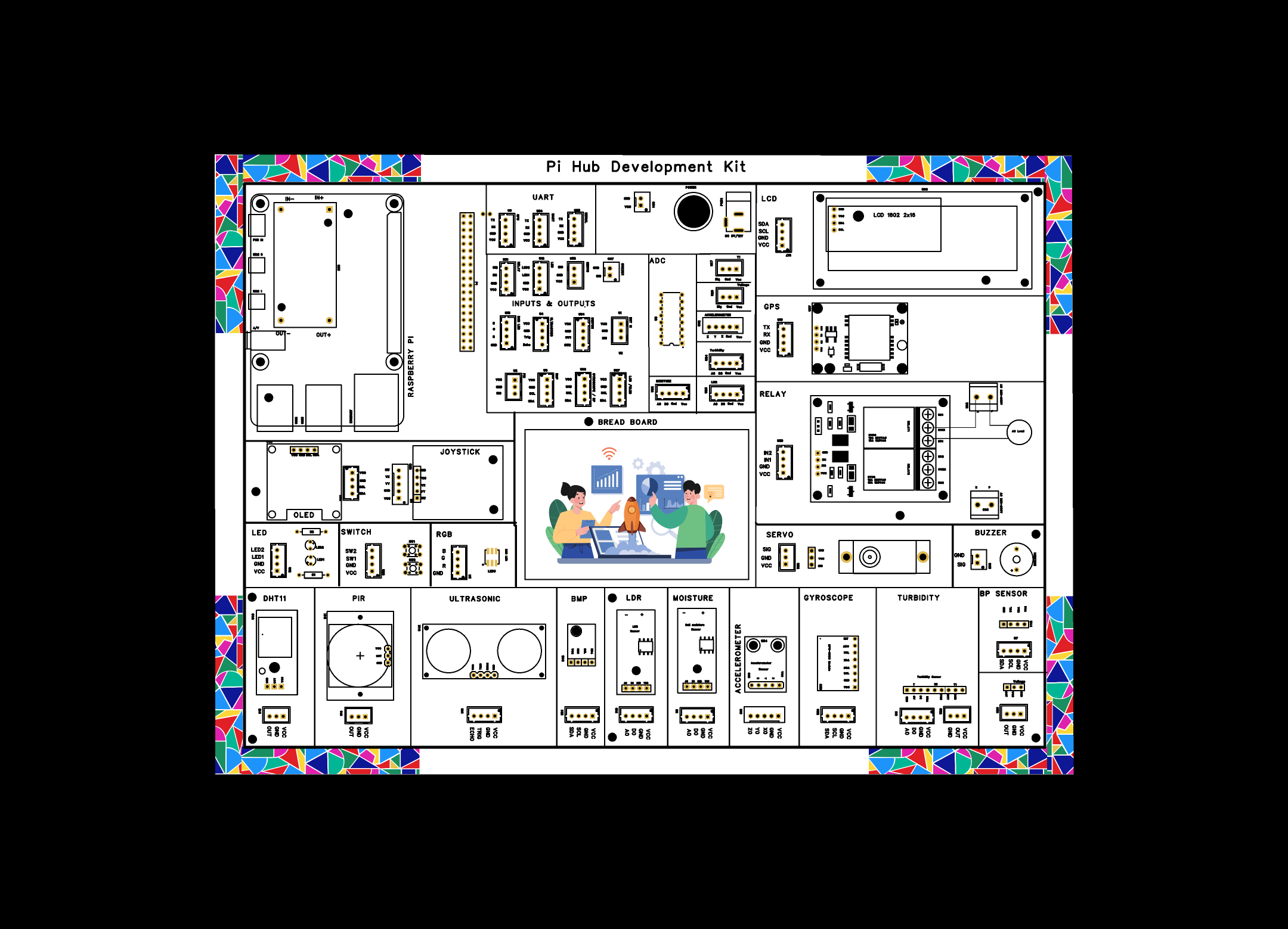
Board Overview- Seamless Raspberry Pi interface with JST connectors
- Over 20 pre-integrated sensors and modules
- Dedicated UART, ADC, and I/O interface sections
- Plug-and-play design with minimal wiring
- Supports Python programming with ready-to-use libraries
- Integrated Breadboard for custom prototyping
- Input Digital mode Sensors
- Input Analog mode Sensors using mcp3008
Full instructions for setup your Pi Hub Development Board
1. Powering the Board
- Ensure the power switch is in the OFF position (not pressed in).
- Connect the 12V 5A DC power adapter to the power jack on the board.
- Plug the power adapter into a standard wall outlet.
2. Powering the Raspberry Pi
- Connect the 5V 3A power adapter to your Raspberry Pi's power input USB-C.
- Plug the power adapter into a standard wall outlet.
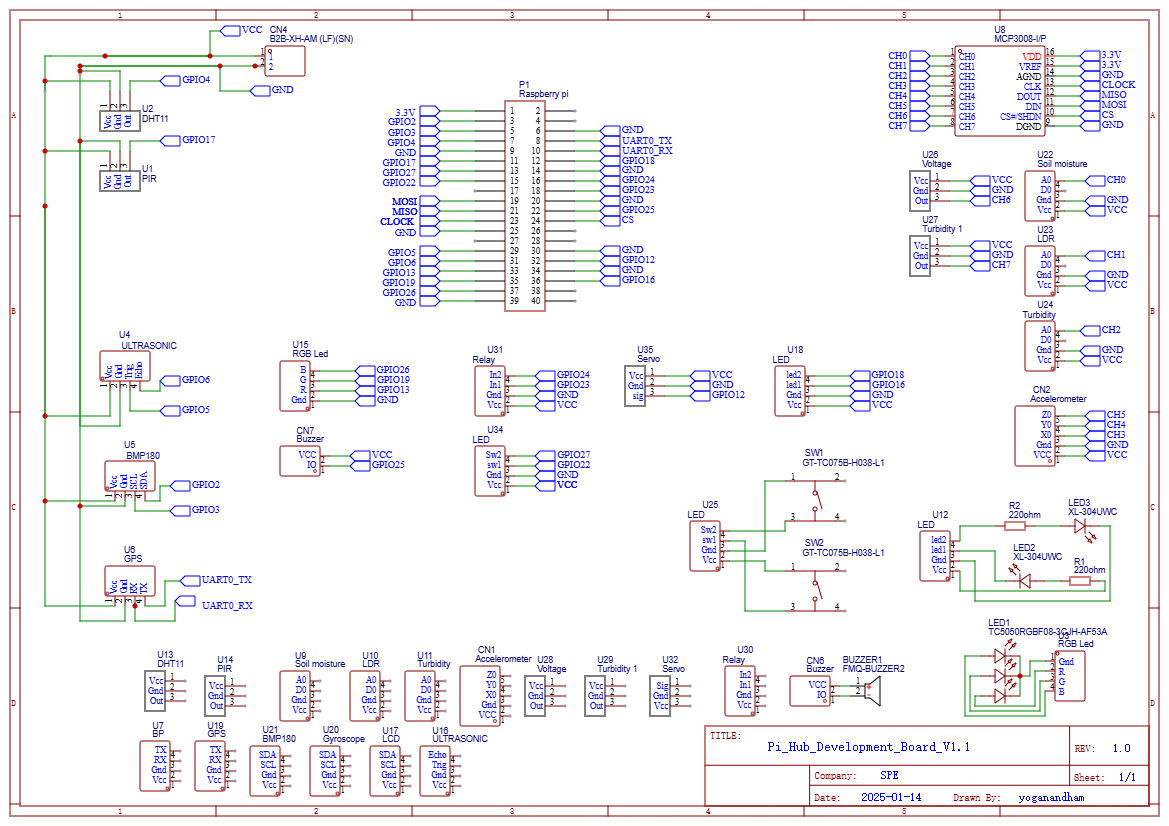
3. Understanding the Wiring Table
We'll use the soil moisture sensor as an example to demonstrate the connection process.
From the connection table:
This means:
- The soil moisture sensor should be connected to JST connector U9 to JST connector U22 on the board
- The A0 pin from the sensor is connected to channel 0 of the MCP3008
- The 16x2 LCD display should be connected to JST connector U17 to JST connector U67 on the board
4. Making the Connection
- Ensure the board is powered OFF before connecting or disconnecting any sensors.
- Locate the soil moisture sensor and its connector cable.
- Find the JST connector labeled U9,U22, U17, U67 on your sensor board.
- Align the moisture sensor as shown in the overview image then use a 4 pin female JST connector from U9 to U22, ensuring the orientation is correct.
- Align the I2C 16x2 LCD as shown in the overview image then use a 4 pin female JST connector from U17 to U67, ensuring the orientation is correct.
- Gently but firmly push the connector into the socket until it clicks into place.
- Double-check that the connection is secure.
5. Connecting the Board to Raspberry Pi
- Ensure both the Raspberry Pi and the board are powered OFF.
- Carefully align the GPIO connector on the board with the GPIO pins on your Raspberry Pi.
- Gently press the connector onto the GPIO pins, ensuring all pins are properly aligned.
- Double-check the connection to make sure it's secure and properly aligned as shown in the below figure.
- Power ON the board by pressing the power button.
6. Installing Required Software
Before using the board, you'll need to install the necessary software on your Raspberry Pi:
- Boot up your Raspberry Pi and open a terminal window.
- Update your system:
sudo apt-get update
sudo apt-get upgrade
git clone https://github.com/yoga495/Pi_Hub_Development_Kit.git
- For more details follow the readme instructions
7. Running the Test Code
- Open a terminal on your Raspberry Pi and navigate to the scripts directory:
cd Analog_Mode_Devices
chmod +x *.py
- Run the moisture sensor test script:
python3 moisture-sensor-test.py
- Run the moisture sensor test script to display on lcd:
python3 moisture-sensor-test.py
8. Interpreting the Results
The moisture sensor test will:
- Display moisture levels on the LCD screen
- Show a percentage value (0% = completely dry, 100% = fully saturated)
- Display a status message (DRY, MOIST, or WET)
Try the following to test your sensor:
- Leave the sensor in air (should read very low moisture)
- Place it in slightly damp soil (should show moderate moisture)
- Place it in a cup of water (should read high moisture)
The process for connecting other sensors is similar to the moisture sensor example. Refer to the above connection table for the specific JST connectors to use.
Enclosure DesignThis project includes CAD files for a custom enclosure designed to house the Raspberry Pi, All sensors and modules in a compact and organized manner. The enclosure consists of a top and bottom part that fit together, providing protection for the electronics while allowing access to all necessary connections.
Enclosure Features- Two-part design (top and bottom) for easy assembly and access
- Mounting points for Raspberry Pi and sensor boards
- Optional screw mounting points for more secure installation


Comments
Please log in or sign up to comment.