Recently I received a Hackster.io logo badge PCB during one of the Arm Innovator Asia Tour events. I'd like to share how I build the circuit of the badge.
Step 1: Figure out design of the badge
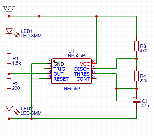
Since the board doesn't come with a schematic, I drew components on a piece of paper and link them according to the PCB.
Step 2: Pick appropriate values of the componentsAccording to the wikipedia page about 555 timer IC, this circuit is 555 timer running in astable mode. I did some search and found some online calculator for 555 astable mode.
My plan was to have the duty cycle to be near 50% and the period to be around 1-2 seconds. Thus I picked a small value for R3 and a large one for R4. By trial and error I came up with:
The period is 1.448s and duty cycle is 50.53%.
There are 2 resistor values left to be decided. When the 555 timer is running, there's a voltage drop. In my case, with Vcc = 5V, the high value of output voltage on pin 3 is about 3.7V, thus I picked different values of R1 and R2, so that the brightness of diode 1 and 2 are similar.
Step 3: Test the circuit on a breadboardBefore soldering all the components onto the circuit board, I tried it out on a breadboard to make sure everything works well.
Test is on a breadboard, it's a bit messy since I don't have short jumper wires :)
Everything works fine, it's time to put it on real circuit board!
- Bend the legs of components and put them through the through-hole on PCB
- Heat up the solder iron and happy soldering :) [sorry I forgot to take a picture about this]
- Trim the legs of components
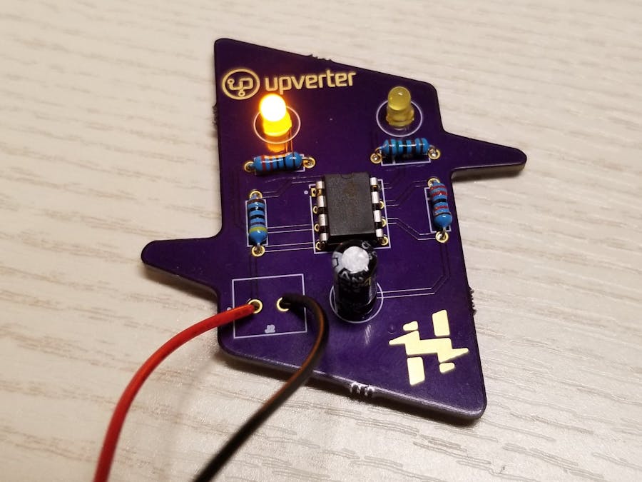
Step 5: Power it up!It's all done. Now we can connect the board to a battery or some other power source. Note the polarity of the connection points marked "J2", positive on the left and negative on the right. I use a 9V battery for this.
The two LEDs are now blinking alternatively. Isn't it cool? :D
Update: Link to a video tutorial "Assembling the Hackster PCB Badge" can be found here.


Comments
Please log in or sign up to comment.