
_cukjzkOQ1S.gif?auto=format%2Ccompress&gifq=35&w=400&h=300&fit=min)

Hardware components | ||||||
 |
| × | 1 | |||
 |
| × | 1 | |||
| × | 1 | ||||
| × | 1 | ||||
 |
| × | 1 | |||
 |
| × | 1 | |||
 |
| × | 1 | |||
| × | 1 | ||||
| × | 1 | ||||
| × | 1 | ||||
| × | 1 | ||||
 |
| × | 1 | |||
Software apps and online services | ||||||
 |
| |||||
| ||||||
 |
| |||||
Hand tools and fabrication machines | ||||||
| ||||||
Jason is an voice controlled assistant app that I coded for Android devices to control the electrical state of an AC appliance, until now it can control lights. You can control the lights from anywhere in the world as long as you have internet connection. This is possible by using an IoT broker, in this case we are using Ubidots.
To use it you need to build the hardware module that connects to the light bulb, (which instructions are in this tutorial) and you will also need to create an Ubidots account.
So let's get started...
Ubidots AccountThe first thing you need to do is go to the Ubidots for Education website and create an account. You can sign in directly if you already have a Twitter, Github, Google or Facebook account.
When you have already created your account you will have access to your token, bu clicking on your username at the top right corner and clicking on API Credentials. Save your token, as we are going to use later on.
The app can be downloaded from the Play Store, it is available in english and spanish.
Copy your Ubidots token into the app, by tapping the settings tab, pasting it in the Ubidots key field and tap the save button.
Now we need to configure a device, go to the devices tab, and tap the add button. Enter a name, preferably the name of the area where the lights are, so you can say "Turn on the kitchen lights". On the ESP32 I/O Pin choose "5", which is going to be the NodeMCU (internal ESP8266) pin connected to the relay. And tap save.
Making the HardwareSafety First
In this project we are working with mains voltage (A/C voltage) which is dangerous if you don't know what you're doing, be very careful. NEVER touch ANY part of the circuit or work with it if it is connected to the wall power. If you don't know what you are doing, stop right here or get some help from professionals.
I am only posting this educational tutorial and I am by no means responsible for any injuries or damage you may cause.
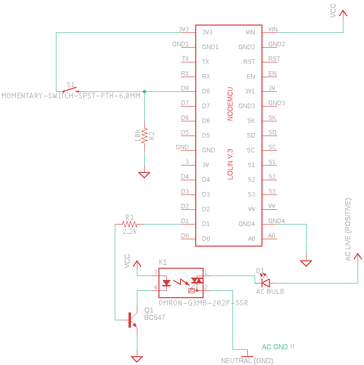
Schematics
- Power the NodeMCU by connecting VIN to VCC (5V) and GND pin to GND.
- Connect D8 to one end of the switch and to a 2.2K Ohm resistor conected to GND.
- Connect the other end of the switch to 3.3V as the NodeMCU can only handle that voltage in its I/O Pins.
- D1 to 2.2k Ohm resistor to the base of the NPN transistor
- Negative DC of the relay to the colector of the transistor.
- Transistor emitter to GND.
- PositiveDC of the relay to 5V.
- Negative of light bulb to one AC pin of the relay.
- Positive of bulb to AC Live (AC Positive).
- OtherAC pin of relay to Neutral (AC Negative).
NOTE: VCC 5V is going to be supplied from an usb cable connected to a simple phone transformer charger.
Breadboard
The switch can be a simple toggle switch or a wall switch, it just needs to detect if the user changes its state so we can still control the lights with a normal switch.
The switch that I used has double throw, we only need one, so I connected its pin 1 to 3V of the NodeMCU and pin 2 of switch to NodeMCU pin D8.
The power supply is going to be a phone wall charger of 5V with a stripped usb cable.
By controlling the ground connection with the relay we can control the AC status of the light bulb.
Before you use the source code, you need to download some libraries:
- Arduino core for ESP8266 (Read the "Installing with Boards Manager" step)
Note: If you don't know how to add libraries to the arduino IDE, you can follow this easy tutorial.
Set your development board to NodeMCU 1.0 (ESP-12E Module).
You need to change some variables in the code:
- Your SSID (Name of your home Wi-Fi network)
- Password of your Wi-FI network
- Your Ubidots token
And finally upload your code to the board.
It works! If you have any questions or suggestions please leave them at the comments section.


Comments
Please log in or sign up to comment.