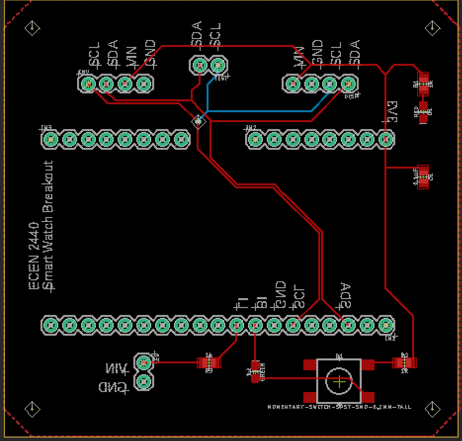
This smartwatch was developed as part of CU Boulder's ECEN 2440: Embedded Systems class. Its design was influenced by Buzz Lightyear's wristwatch in Pixar's Toy Story. The watch uses an OLED display, ICM-20948 IMU, an ESP32, an Adafruit laser, and a custom PCB. The OLED displays the current time and angular velocity of the wristwatch while a button on the PCB can control the laser, firing in 3 second periods.
Our first hurdle in the software of this project was to flash the ESP32 memory to allow us to program in Micropython. One of our learning objectives was to learn Micropython and gain experience using the Thonny IDE to upload to our board. The ESP32 is originally programmed to be developed using the Arduino IDE, so first we had to erase the flash on the ESP32 and write to the flash the Micropython boot.
Once Micropython was installed, we began learning Micropython using the Thonny IDE. We all wrote basic scripts to test each of our components separately to ensure they all worked properly and we understood how to use them. We took advantage of an OLED library as well as a library for our IMU with slight modifications.
Our biggest hurdle was being able to communicate with our IMU. Our IMU library contained a class that automatically detected an I2C bus and began using that to communicate; however, we could not get the class to function properly so we decided to alter the library by writing out own I2C functions and instead of automatically detecting the I2C bus, we initialized it with the bus we were using. This allowed for the code to compile, but we once again ran into issues. Our first issue was that our IMU's default address was its alternate address listed on the datasheet. We solved this issue by printing the addresses on the I2C bus using the i2c.scan() function and realized that we were not talking to the write address. After we addressed this problem, our I2C functions that we wrote were returning bytes objects rather than integers and then failing our comparisons and reading junk. We fixed this issue by converting our bytes object to an integer after it was read.
We then applied our new knowledge of interrupts and Micropython to integrate all of our code together in order to print the real time, the angular velocity in the x direction, and allow for the button to fire the laser for 3 seconds. Overall, our project was a success because we completed all of our initial requirements as well as focusing on our learning objectives to get the most out of the experience.
Functional Block Diagram:
Our highest level software diagram:
The software diagram for I2C Communication Protocol:
This is the software diagram for the Display integration:
IMU Software Integration:
Laser Software Integration diagram:
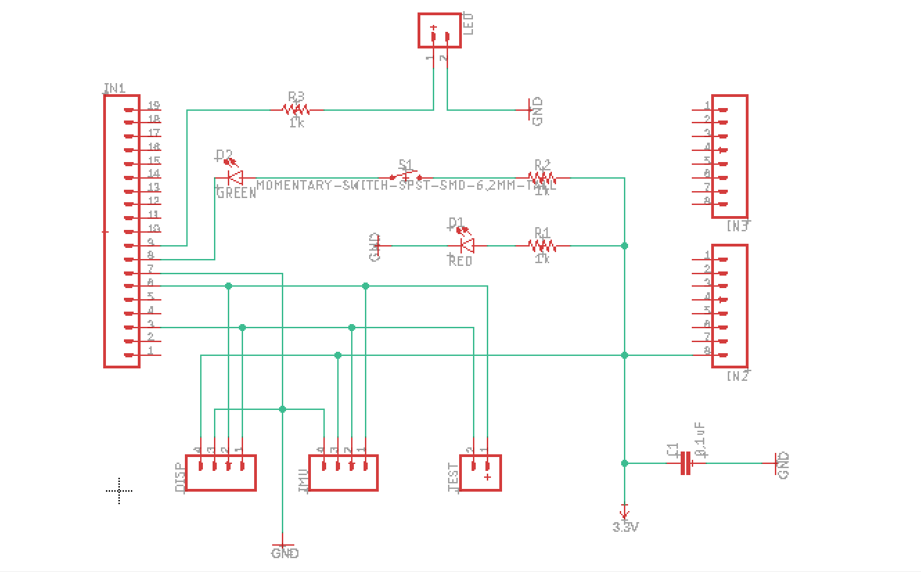
Wiring Diagram:
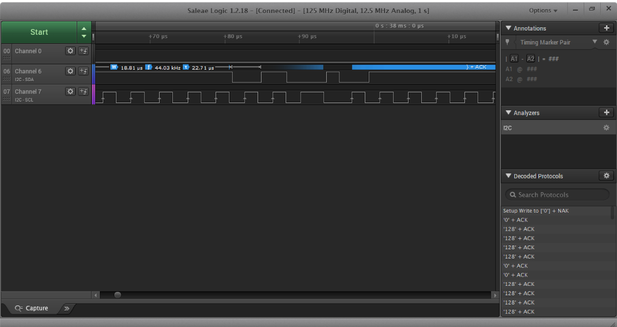
Logic Analyzer:
In order to visualize and debug our I2C communication between our OLED and IMU we used a Saleae Logic Analyzer. This allowed us to see both the SCL and SDA lines as well as making sure the slave was sending ACK signals. In this figure, we were testing out OLED using our real time clock code. The logic analyzer was easy to set up due to our PCB design which allowed testing points on our SDA and SCL lines for easy access.
Debugger:
Because of our choice to code in Micropython, we had to use another development environment called Thonny. This IDE can also be used for Python and its debugger was very helpful in learning the basics of the language. However, the debugger does not support Micropython and was disabled when using the Micropython interpreter. Our solution was to use print statements to visualize what was happening in our code. This was especially helpful during our I2C debugging process when our I2C read function was returning a bytes object instead of an integer. Using the Thonny Shell, we saw that the print statement looked different than other integers and learned about the bytes object and how to convert it to an integer. Overall, the print statement, although tedious and reliant on an idea of what the problem is, worked fine to debug during this project.
Appendix:
- ESP32 Technical Reference Manual📷
- MicroPython Reference
- IMU Datasheet
- IMU Hookup
- OLED tutorial with python
- IMU Library
- MicroPython Firmware
- SSD1306 Library
- ICM-20948 Library (Original, before edited)


_t9PF3orMPd.png?auto=compress%2Cformat&w=40&h=40&fit=fillmax&bg=fff&dpr=2)


_3u05Tpwasz.png?auto=compress%2Cformat&w=40&h=40&fit=fillmax&bg=fff&dpr=2)
Comments