Shared office spaces like conference rooms, microwaves, and even bathroom stalls can present resource contention problems that span from mild annoyance to downright messy. I have an office at WeWork in downtown Nashville, we are a remote team for Tektronix in Portland, Oregon. That means we spend a lot of time on Skype, phone, or some other voice/video tech. WeWork has banks of personal "phone booths" meant for a single person to take a call without disturbing others. This project is a prototype IoT occupancy sensor that shows whether phone booths are available for use before trekking across the building, finding out you need other arrangements, and showing up late to an important conference call.
You can see the actual final product on a real-time dashboard here: https://go.init.st/7y94ii3
The IoT occupancy sensor unit is made with a Kemet Pyroelectric Infrared Sensor connected to a Pi Zero W board inside a custom 3D printed enclosure. The phone booths have USB charging ports in a perfect spot to mount the device and run a short miniUSB power cable. The on-board software joins the WiFi network and runs a python script on power up. Data from the sensor streams to Initial State where we create and share an anywhere-accessible dashboard of the real-time occupancy status. We printed a QR code on the device so anyone can quickly find the dashboard with their phone.
The sensor gives 200ms pulses according to movement and temperature changes in its field of view. Measuring the waveform with an Oscilloscope gives you a good idea of the simplicity of the output. I am using a Tektronix 5-Series to do the measurement. This gives a better idea of how the software should work.
The module comes with a connector, but for quick prototyping you'll need to breakout the connector to something you can easily breadboard with and eventually solder for that protoype-y yet sturdy solution solution. The last thing I wanted to do is spend a lot of time trying to deal with tiny pads on the module, connected to tiny breakable wires during the software phase. I combined the following items to create a durable connectivity solution
- Shortest mating cable available (2") - https://www.digikey.com/product-detail/en/jst-sales-america-inc/A05SR05SR30K51A/455-3713-ND/6708471
- Mating Connector - https://www.digikey.com/product-detail/en/jst-sales-america-inc/SM05B-SRSS-TB(LF)(SN)/455-1805-1-ND/926876
- 1MM Breakout board to Through-hole bliss - https://www.amazon.com/gp/product/B0191ELG4Y/ref=ppx_yo_dt_b_asin_title_o01_s00?ie=UTF8&psc=1
I soldered the connector to breakout board without even needing my glasses.
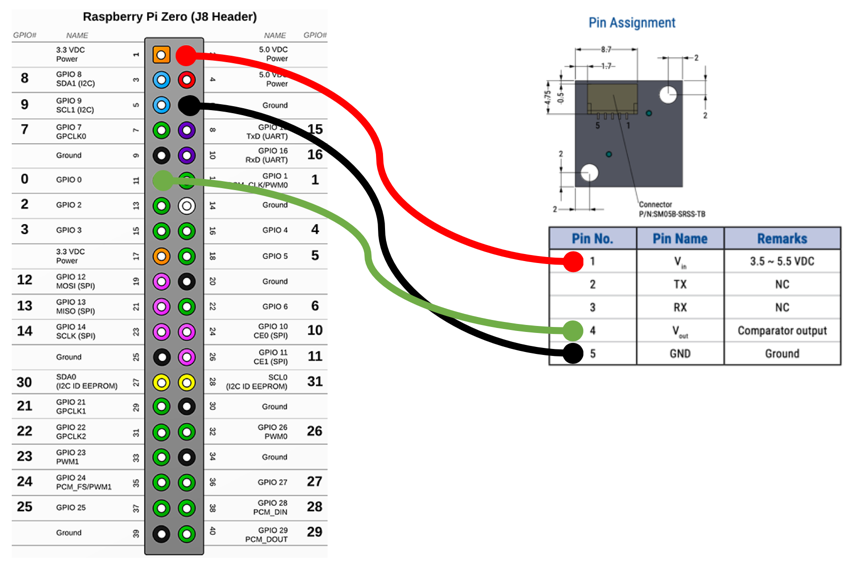
Connect the power pin of the sensor to 5V, Ground to Ground, and connect the output line to GPIO 0 of the pi Zero board.
The sensor has a straightforward output that can be read using a simple GPIO line (see the o-scope trace above). 200ms is a plenty-slow-enough signal to use loop-timed direct software sampling. No fancy protocols or hardware sampling needed. I just decided to make my main loop sample at 195ms. Sure it catches a level twice here and there, but you'll avoid getting sample-synched on the 200ms edge, which is certain to be one of those intermittent-impossible-debugging-rabbit-holes your mama told you about.
After some experimentation, the algorithm is pretty solid and fairly simple. You'll find that there are more pulses when movement is present (of course), but also 2 consecutive HIGH levels is especially representative of movement. I count both pulse and consecutives and give the consecutive pulses 15x the weight of a single pulse. Here is how it works. There are three counters that run inside the 195ms loop.
- occupancy_check - Loop counter that start back at zero every OCCUPANCY_CHECK_INTERVAL. This defines the interval to send data and check occupancy. The code here has an OCCUPANCY_CHECK_INTERVAL of 27 which means the actual time is 27*195ms or 5.2 seconds.
- motion_samples - Stores a count of the HIGH pulses that occur during the occupancy check interval.
- consecutive_check - Stores a count of the number of times consecutive pulses occur. Since these represent a much higher likelihood of important movement characteristic, the code increments motion_samples by 15 for each occurrence.
Ultimately, the counter "motion_samples" is streamed to our dashboard as a combined count of all the 200ms pulses and the consecutive pulses weighted by 15x. By streaming this raw number, we can use Real-Time Expressions in Initial State to determine "Occupied" or "Available" (discussed later in the article). That way we can remotely change the threshold without changing the code.
Here is the main loop code snippet. The full code is attached to this project.
This software is certainly still a prototype, but there are a number of things you can do to make your life easier, and make your code more resilient.
1 - Learn how to connect your headless pi Zero W to wifi on boot - https://core-electronics.com.au/tutorials/raspberry-pi-zerow-headless-wifi-setup.html
2 - Go through the Pi Process Tutorial found here - https://github.com/initialstate/pi-process-dashboard/wiki/Part-1.-Initial-State
You will achieve the following:
- If you don't already have one, this tutorial will walk you through getting a free Initial State account.
- Monitor your process (status of your running code) from the same dashboard where your data is streamed.
- Monitor the IP Address of the hardware. In many network environment DHCP can change your IP, and you'll have to go and find it, if you want to remote back in.
- Launch a monitored process on boot.
Once you do the two items above. You can power cycle your device and it will:
- Connect to WiFi.
- Run your Python script.
- Automatically monitor the state and IP Address of the device(s)
Even a power outage will bring your device back up to a known state and start sending data automatically once power is restored.
Initial State DashboardThis real magic of this project is that anyone can check on the status of the WeWork phones from anywhere. This is accomplished by streaming data to Initial State. Go to iot.app.initialstate.com and create a new account or log into your existing account.
Once you have an account you need to install the ISStreamer on your Raspberry pi. Repo and tutorial can be found here: https://github.com/initialstate/python_appender
Once ISStreamer is installed you will be able to import and stream with the simple interface shown below. See the Python implementation of this project in the attached code at the bottom.
from ISStreamer.Streamer import Streamer

# create or append to a Streamer instance
streamer = Streamer(bucket_name="Some Bucket Name", bucket_key="bucket_key", access_key="YourAccessKey")

# send some data
streamer.log("test", "hi")
streamer.log("temperature", 32)

# flush data (force the buffer to empty and send)
streamer.flush()

# close the stream
streamer.close()
Once you have some signals in an Initial State dashboard the world is your oyster. In this project:
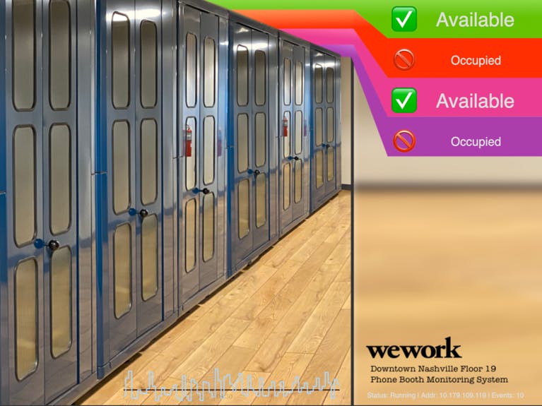
- I imported a custom background image to show the phone booths
- Showed some diagnostic information in bottom of the screen.
- Used both words and icons (emojis) to represent the occupancy of the phone booth.
- Go Nuts and try some things for yourself.
CURRENT LIVE DASHBOARD - https://go.init.st/7y94ii3
If you remember, the Python script is sending that counter variable called "motion_samples" to the dashboard. We are not pre-calculating occupancy on the device so that we can experiment easily in different environments, lighting, and situations without changing the code. In Initial State we utilize a feature called Real-time Expressions, which is essentially in-line math you can write against any signal in your dashboard.
To change "motion_samples" count into the occupancy state we chose a threshold of 30 and wrote math on the incoming data to do two things
- Smooth the incoming data with some averaging. The can slow the detection time, but it improves accuracy and removes noise.
- Calculate a simple yes/no by saying: IF smoothed motion_samples > 30 "Occupied", IF <=30 then "Available". Of course, we can experiment quickly with different thresholds since it's available in the cloud rather than in the code of the device.
Here is what is looks like to in our dashboard resolving the raw data to an emoji icon.
Lastly, Let's talk about the enclosure that is custom printed to fit our boards and provide mounting options. See the final result with build steps in the image carousel below:
We started with a design by Geraldo Ramos posted on Thingiverse for a camera mount and pi zero W enclosure. We remixed the files to hold the KEMET sensor instead of the camera, and printed it using an Ender 5 3D Printer (https://www.amazon.com/Creality-Ender-Plus-3D-Printer/dp/B07XKZW9KX). All 3D files are attached to this project.
Our enclosure has two mounting options.
- Mount flat on surface.
- Swivel Mount Option to gain control of the direction and viewing angle of the device. This is the reason for the pillow blocks on the side.


Comments
Please log in or sign up to comment.