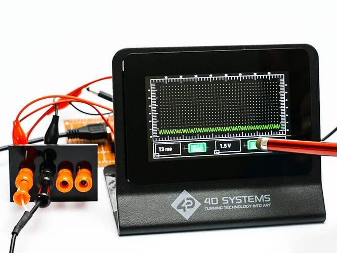
In this project, we will make a single trace oscilloscope using the gen4-uLCD-43DCT-CLB display module. The gen4 HMI display module will be used for showing the waveforms of small signals. The scope also has an additional function for scaling the waveform to be displayed.
Components- gen4-PA and FFC Cable
- uSD Card
- uUSB Cable
- 5 V external power supply
- Jumper Wires
- 2 x Test probes
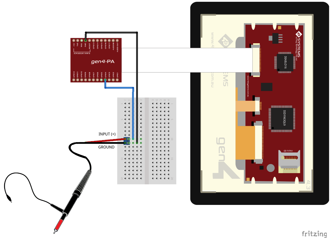
Build the circuit as shown in the diagram.
- Download the project file here.
- Open the project using Workshop 4. This project uses the Visi Environment.
- You can modify the properties of all the objects and buttons using the object inspector.
- You can change the trigger voltage level at which the scope will start sampling and showing the input signal waveform. The trigger level that can be used ranges from 0 to 4095 which relates to the analog voltage of 0 V to 3.3 V (Highlighted in the Yellow box). The default time and voltage scaling after booting the scope can also be changed if needed (Highlighted in the Red box).
- The pin assignment for the analog input in the line shown below. You may choose from pin PA0 to PA3 as the scope input. (Caution: GPIO pins can only handle up to 5 volts, additional protection or isolation is needed for measuring higher voltages)
- You can change the time division scaling of the scope in the lines shown below, use a positive integer to expand or a negative integer to compress the waveform. (Note: Be aware that negative values significantly increase the amount of internal memory required to hold scope values and that such values should be used carefully.)
- You can also change the voltage division by amplifying or attenuating the waveform. The waveform voltage level can be attenuated by using values below 100, and by using values from 100 up to 200.
- You can also change the time division scaling to be displayed in the status bar if necessary.
- You can also change the voltage division scaling to be displayed in the status bar if necessary.
- You can also change the background image, the scope trace and graticule color, and the buttons of the oscilloscope.
- Click on the “Compile” button.
Note: This step could be skipped. However, compiling is essential for debugging purposes.
Step 4: Comms Port- Connect the display to the PC. Make sure that you are connected to the right port. Red Button indicates that the device is not connected, Blue Button indicates that the device is connected to the right port.
- Go back to “Home” tab. This time, click on the “Comp’nLoad” button.
- Workshop 4 will prompt you to select a drive to copy the image files to a uSD Card. After selecting the correct drive, click OK.
- When the micro SD card is not yet inserted, this message will appear on your gen4 Display:
"DRIVE NOT MOUNTED"
- After inserting your micro SD card this GUI should appear on the gen4 Display:


Comments
Please log in or sign up to comment.