


Hardware components | ||||||
 |
| × | 1 | |||
 |
| × | 1 | |||
 |
| × | 1 | |||
 |
| × | 1 | |||
 |
| × | 1 | |||
 |
| × | 2 | |||
 |
| × | 1 | |||
 |
| × | 1 | |||
 |
| × | 1 | |||
|
| × | 1 | |||
As a high school junior, I'm really interested in both biology and engineering, and I'm always looking for ways to combine them. I'm especially fascinated by bioluminescence – how some living things can create their own light. Recently, I've started exploring Arduino as a way to bring some of my biology-related project ideas to life. This project is a collaboration between me and my dad, who has experience with electronics and is acting as my instructor. He introduced me to Arduino and AI, with the goal of helping me learn how to use these tools for my future career in biology. We utilized Gemini, an AI assistant, as a tool to help us bring our ideas to life. Gemini's role was to assist with tasks like generating code, creating Arduino sketches, and drafting parts of the report, but always under our direct guidance and based on our original concepts. While my interests in biology drove the project, this report is a reflection of our combined efforts and ideas.
To start, we used Gemini to brainstorm project ideas that combine bioluminescence and Arduino. It was really helpful to learn how AI can be used in the research process. My dad provided me with a list of the 31 science projects in a Google Doc. This helped me understand different ways I could explore this area. Here are a few of the project ideas that the AI assistant came up with that really sparked my interest:
- Air Quality Monitor: Measure air pollutants like particulate matter (PM) and carbon dioxide (CO2) levels.
- Biofeedback Device: Use sensors to measure physiological parameters like heart rate variability (HRV) and provide feedback for relaxation techniques.
- Microbial Fuel Cell: Generate electricity from bacteria using a microbial fuel cell and Arduino.
- Plant Watering System: Monitor soil moisture and automatically water plants when needed.
- Heart Rate Monitor: Measure heart rate using a pulse sensor and display it on an LCD or LED display.
- Temperature & Humidity Logger: Record temperature and humidity data using sensors and store it on an SD card.
I looked at the list provided and chose 15 independent research projects. I went through the list and choose some I thought were interesting, the bioluminescent night light was on the list. The overall idea was to ascertain which projects were the most scientific and related to biology. We also wanted to create a project that was unique. My father, Gemini (our AI assistant), and I created a list of materials, instructions, key details, and any other data that would be useful for successfully and efficiently completing this research project.
I chose the bioluminescent night light project because it combines my interests in biology and Arduino. I recently completed a dual enrollment Biology 2 lab course, which sparked my interest in bioluminescent organisms like Dinoflagellates. Learning about fascinating creatures such as Dinoflagellates is a personal hobby of mine. I love biology, more specifically microbiology, so this project caught my eye. I have been experimenting with Arduino for the past year now and have grown to really enjoy creating projects with it. I love working with my hands and building things. Out of all the projects Gemini provided, this one definitely stood out to me because it combines two of my favorite new hobbies. With the project chosen, I began incorporating AI, specifically Gemini, into my research. This project was structured to help me develop skills in using AI for coding, circuit design, research, and writing. Gemini became my primary tool for these tasks, and this bioluminescent night light project served as a learning platform for me to explore AI's capabilities in a scientific context. I started my research of the following items according to my AI assistant:
- Components needed
- Cost for parts
- Steps
After Gemini helped us brainstorm initial project ideas, we continued to collaborate with the AI. By keeping Gemini informed of our design iterations in separate conversations, we were able to refine the project and determine that a two-version approach was optimal.
Version 1 (Prototype without Bacteria):
An LED simulates the bioluminescent bacteria. The light sensor/photoresistor detects the light from the initial LED. This triggers the Arduino to activate a second LED to indicate that light was sensed.
Version 2 (Final with Bacteria):
Actual bioluminescent bacteria now provide the initial light source. The light sensor/photoresistor detects the light from the bacteria. This triggers the Arduino to activate a separate set of LEDs creating a night light.
Informing Me:My father listed what I would learn before I started this project. He wanted me to understand its purpose and think out of the box. Below is the list:
- How to use AI to make science projects that require a skill you do not yet have.
- How to start using Arduino hardware and software to make science projects.
- Biology and thinking in a scientific manner.
These topics gave me a goal and helped me focus and get a better understanding of how to use Arduino within the field of biology. Furthermore, I had to learn how to speak to my AI assistant throughout this project. My father provided me with questions to ask my AI assistant as I progressed throughout:
- How do we make this a great and fulfilling biology project (How/What do we collect, add, enhance, etc.?)
- What are all the parts we need to build the version without bacteria?
- Do you understand the value and purpose of this project?
- Can you clearly explain what this project is and its scientific purpose and value?
As I embarked on my research, I quickly discovered that effectively using Gemini required a learning curve. Initially, Gemini sometimes provided incorrect, vague, or overly broad answers. I learned that the key was to refine my prompts, using precise language and providing specific context to guide Gemini towards the information I needed. For example, when I first asked for a list of components, Gemini provided a comprehensive list of components, including many that were ultimately unnecessary for this project, such as general-purpose diodes (e.g., 1N4001), heat shrink tubing, and transistors.
At that stage, I trusted Gemini's suggestions as accurate. However, when my dad reviewed the list, he realized it included many inessential items. He helped me narrow down the components to only those that were truly required, giving me a clearer understanding of the project's needs. This also helped me learn how to better evaluate information provided by AI. Through this process, I developed a better understanding of how to structure my questions and instructions to elicit more accurate and relevant responses from Gemini. This process of learning how to effectively interact with AI became an integral part of the project itself.
Project Management:My dad and I are geographically spread out, so we had to figure out a way to work on this project online and keep costs down. We knew the bioluminescent bacteria we wanted to use would be pretty pricey, and we were still learning about the specific scientific requirements for the project.
My dad made a central sheet listing components and made a checklist of what we already had. Here is a screenshot of a section of that sheet:
Then we had to research where we could get the bacteria. He began populating the sheet with more information he thought would be useful.
Version 1: Proof-of-Concept Prototype (or LED Prototype)Our initial idea was to have the bacteria light up, and then have that light trigger a second LED, which would be the actual night light. We didn't want to jump into buying the bacteria only to find out later that our idea wouldn't work. So, we decided to do a test run first, a kind of "proof of concept." Before spending money on the actual bacteria, we used an LED to act as a proxy—basically, a substitute—for the bacteria's light. The plan was for this first LED (the bacteria's stand-in) to light up. Then, a light sensor would detect that light and trigger a second LED. This second LED was our proxy for the real night light we wanted to build. We used a 5528 photoresistor, also called a light-dependent resistor (LDR), to detect when the first LED was on. This way, we could test our idea and make sure the light sensor and the LEDs were working together correctly before getting the actual bacteria.
It was difficult for me to create a circuit diagram needed for the layout of how the breadboard was supposed to look because I was focused on the bioluminescent version and searched for similar projects with that name but I couldn’t find one. My dad introduced me to Tinkercad so I could create an initial circuit.
Iteration 1.1: Initial Circuit (Series Error)I used Gemini to help me create a circuit in Tinkercad but Gemini gave me an incorrect circuit. It created a circuit in series instead of in parallel. I successfully made my first circuit in Tinkercad using Gemini to assist, but the circuit created by Gemini was not the best approach. Below is the circuit with the LEDs in series.
My father reviewed it and realized that he should jump in to keep things moving. He redid the circuit I made in tinkercad on Dec. 19, 2024. He used an Arduino Uno in the Tinkercad circuit because Tinkercad does not have a Nano. I am using a Nano for my build. I then recreated the circuit on my own and made the circuit below:
I connected the Nano off to the side of the breadboard but not on it creating potentially loose connections.
My father realized that a layout for use with a Nano would be easier for me so he made another with a Nano on a breadboard.
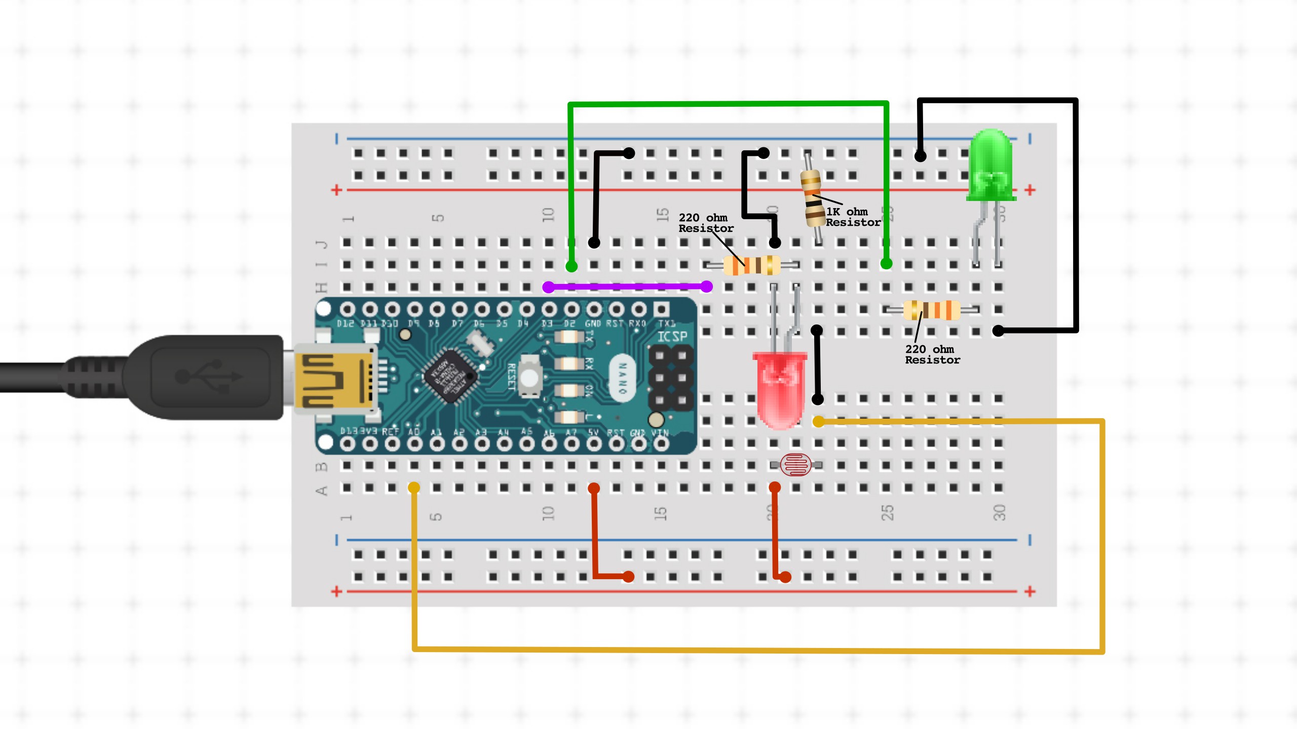
He designed the layout piece by piece in Circuito.io because Cirtuito.io has the option to use other Arduino boards including the Nano. He exported screenshots one component at a time and then used Inkscape (a free vector graphics program similar to Illustrator) to draw out the layout and wiring. However, in that layout, he connected the red LED to the resistor incorrectly. He connected the 220 ohm resistor to the red LED’s cathode instead of the anode. Here is the initial layout:
Iteration 1.3: Nano on Breadboard (Resistor Placement Error)My dad insisted that I redo the circuit and place the nano on the Breadboard instead of off to the side. He stated that placing the Nano on the board would help make stronger connections and make the overall prototype neater. Below is my newer circuit with the Nano on the breadboard:
Obviously, because we connected the red LED and its resistor incorrectly, and the photoresistor was pointed away from the yellow LED, this version didn’t work as expected.
Below is a video of how the breadboard looked and worked when I plugged the USB into my laptop to see if it would work correctly:
Video:Reassembly, Error, and CorrectionThe next day, I started this project up again. Another issue was that I had disconnected all the components from the breadboard the night before. This mistake led to time wasted the following day when I again tried to recreate the layout on the breadboard. It also opened the door for new connection mistakes. Below is the new connected circuit the next day.
This is only my third Arduino project and in the second try at creating the circuit, I made the mistake of connecting the components incorrectly on the breadboard. My father reviewed all pictures of the circuit on the breadboard to make sure it was all connected correctly.
Because I had to reconnect everything again, I introduced a new problem. I connected the photoresistor incorrectly. The leg on the right should have been in row 22 instead of where it is in the photo above in row 21.
After I had put the components back on correctly, we noticed that the indicator LED stopped working. Notice that the indicator LED in the initial reassembled circuit, 3 images above, is blue. We decided to troubleshoot using a new sketch to test if both LEDs were functional. We wanted to know if they would just blink, which would tell us if it was either an issue with the LEDs or the wires. We used a temporary sketch to test if they were working. Below is the code my father had our AI assistant create and I used to test if the LEDs were in functional:
LED Test Sketch:const int bacteriaLedPin = 3; // Pin connected to the "bacteria" LED
const int nightLightLedPin = 2; // Pin connected to the "night light" LED
const unsigned long onTime = 5000; // Time in milliseconds both LEDs will stay ON
void setup() {
pinMode(bacteriaLedPin, OUTPUT); // Set the bacteria LED pin as an output
pinMode(nightLightLedPin, OUTPUT); // Set the night light LED pin as an output
}
void loop() {
// Turn both LEDs ON
digitalWrite(bacteriaLedPin, HIGH);
digitalWrite(nightLightLedPin, HIGH);
// Keep them ON for 5000 milliseconds (5 seconds)
delay(onTime);
// Turn both LEDs OFF
digitalWrite(bacteriaLedPin, LOW);
digitalWrite(nightLightLedPin, LOW);
// Wait indefinitely (or add another delay here if you want to repeat the cycle)
while (true); // This creates an infinite loop, keeping the LEDs off
// or
// delay(5000); //To turn them back on after 5 seconds and repeat
}It turned out that the blue indicator LED had to be switched out along with two connecting wires just to be sure. Notice the new green LED in the photo above. Once we swapped out the LED and jumper wires, we ran the LED sketch again and it worked. The new green LED lit up.
Iteration 1.4: LED Timing Fix - AI to the Rescue!We uploaded the original code and we faced another dilemma: the LEDs were fully functional but were alternating and lighting up at different times. My father gave the code to our AI assistant and had it tell us the problem. We were advised to change the light threshold from 1000 to 500 and below is the final code for the bioluminescent night light project. The correct layout for this project and sketch are shown below:
Layout:/*
Bioluminescent Night Light with LED Proxy (Version 1.4)
BiotronikMAiker
This project simulates a bioluminescent night light using LEDs and a photoresistor.
An LED acts as a proxy for bioluminescent bacteria, turning on and off at set intervals.
A photoresistor detects the light from the "bacteria" LED.
When the "bacteria" LED is on and the ambient light is low, a second LED (the "night light") is activated.
This code was generated with the assistance of Gemini, an AI assistant, under the guidance and direction of BiotronikMAiker and VideotronicMaker.
It is part of a larger project exploring the integration of bioluminescence, Arduino, and AI.
Circuit:
- Bacteria LED (e.g., white or yellow) connected to digital pin 3.
- Night Light LED (e.g., green) connected to digital pin 2.
- Photoresistor connected to analog pin A0.
Version 1 - Prototype without Bacteria:
An LED simulates the bioluminescent bacteria. The light sensor/photoresistor detects the light from these initial LEDs.
This triggers the Arduino to activate a single LED to indicate that light was sensed.
Modifications by: VideotronicMaker (Instructor)
Date: [January 7, 2025]
*/
// Pin definitions
const int bacteriaLedPin = 3; // Digital pin connected to the "bacteria" LED (simulating bacteria)
const int nightLightLedPin = 2; // Digital pin connected to the "night light" LED (indicator)
const int photoresistorPin = A0; // Analog pin connected to the photoresistor
// Timing constants (in milliseconds)
const unsigned long onTime = 3000; // Time the "bacteria" LED stays on (3 seconds)
const unsigned long offTime = 2000; // Time the "bacteria" LED stays off (2 seconds)
// Light threshold for the photoresistor.
// Adjust this value based on your photoresistor and ambient lighting conditions.
const int lightThreshold = 500;
// Variable to store the last time the "bacteria" LED was updated
unsigned long previousMillis = 0;
// Variable to track the state of the "bacteria" LED (on or off)
bool bacteriaLedState = HIGH; // Start with the "bacteria" LED ON
void setup() {
// Initialize the "bacteria" LED pin as an output.
pinMode(bacteriaLedPin, OUTPUT);
// Initialize the "night light" LED pin as an output.
pinMode(nightLightLedPin, OUTPUT);
// Turn on the "bacteria" LED initially.
digitalWrite(bacteriaLedPin, HIGH);
}
void loop() {
// Get the current time in milliseconds.
unsigned long currentMillis = millis();
// --- Bacteria LED Control ---
// Check if the "bacteria" LED is currently ON and if the 'onTime' duration has elapsed.
if (bacteriaLedState == HIGH && currentMillis - previousMillis >= onTime) {
// Update 'previousMillis' to the current time.
previousMillis = currentMillis;
// Change the state of the "bacteria" LED to OFF.
bacteriaLedState = LOW;
// Turn OFF the "bacteria" LED.
digitalWrite(bacteriaLedPin, bacteriaLedState);
}
// Otherwise, check if the "bacteria" LED is currently OFF and if the 'offTime' duration has elapsed.
else if (bacteriaLedState == LOW && currentMillis - previousMillis >= offTime) {
// Update 'previousMillis' to the current time.
previousMillis = currentMillis;
// Change the state of the "bacteria" LED to ON.
bacteriaLedState = HIGH;
// Turn ON the "bacteria" LED.
digitalWrite(bacteriaLedPin, bacteriaLedState);
}
// --- Photoresistor Reading ---
// Read the analog value from the photoresistor.
int lightLevel = analogRead(photoresistorPin);
// --- Night Light LED Control ---
// Check if the light level is below the threshold AND the "bacteria" LED is ON.
if (lightLevel < lightThreshold && bacteriaLedState == HIGH) {
// Turn ON the "night light" LED.
digitalWrite(nightLightLedPin, HIGH);
} else {
// Turn OFF the "night light" LED.
digitalWrite(nightLightLedPin, LOW);
}
}The Bacteria Proxy LED, photoresistor and LED indicator finally worked as expected. The yellow Bacteria LED lit up for 3 seconds, the photoresistor sensed it and triggered the night light to light up for as long as the bacteria was lit. Then the bacteria LED turned off for 2 seconds, the photoresistor sensed that and turned off the night light. Below are some pictures of the layout and a video of how it should look:
Video:Final Circuit Images:As the project stands now as a night light project, it would be more suited as a design project and less of a biology project. Following some brainstorming sessions with Gemini, my father and I made the decision to enhance the project so that it would be more of a biology project. In my next post, I will share the details of this new version.


Comments