


Hardware components | ||||||
 |
| × | 1 | |||
Software apps and online services | ||||||
| ||||||
Hand tools and fabrication machines | ||||||
 |
| |||||
Greetings everyone, and welcome back.
This is the PowerPulse Inverter project, a simple and effective way to convert 12V battery power into a stable AC voltage.
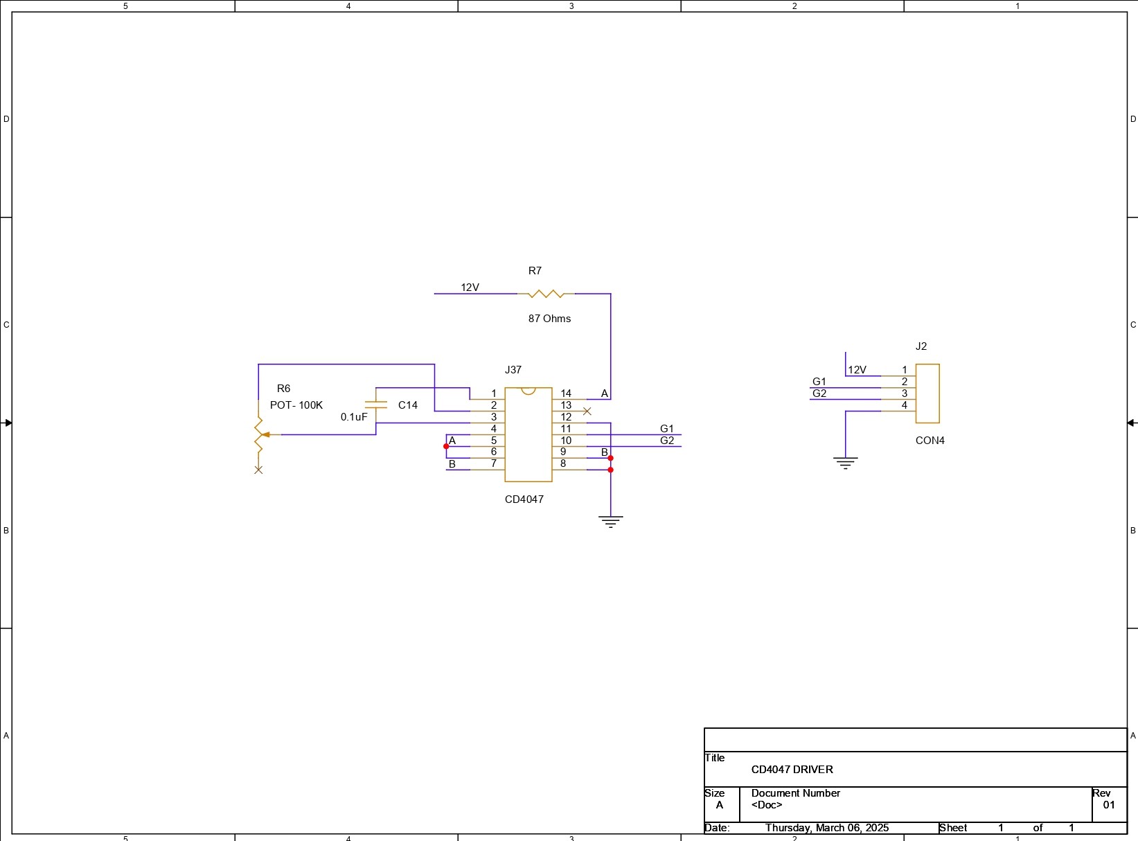
This unique inverter design utilizes the CD4047 IC to generate precise square wave pulses with powerful MOSFETs and a 12-0-12V transformer to achieve an adequate AC output.
The PowerPulse Inverter enhances heat management, troubleshooting, and updates by separating the circuit into two primary sections for modularity: the CD4047 Driver Circuit and the Mosfet Board.
This project is about the whole build process of this inverter circuit, so let's get started with the build.
Materials requiredThese are the materials used in this build:
- Custom PCBs (got from PCBWAY)
- CD4047
- 10K SMD Resistors
- IRFZ44N Mosfets
- 12-0-12 Transformer
- 82 Ohms 1W Resistor
- MOV
- 100k Potentiometer
- 100nF capacitor
- M7 DIODE
- PUSH on/off switch
- CON2 Screw terminal
- AC BULB
- AC BULB Socket
- 12V Lithium Battery Pack
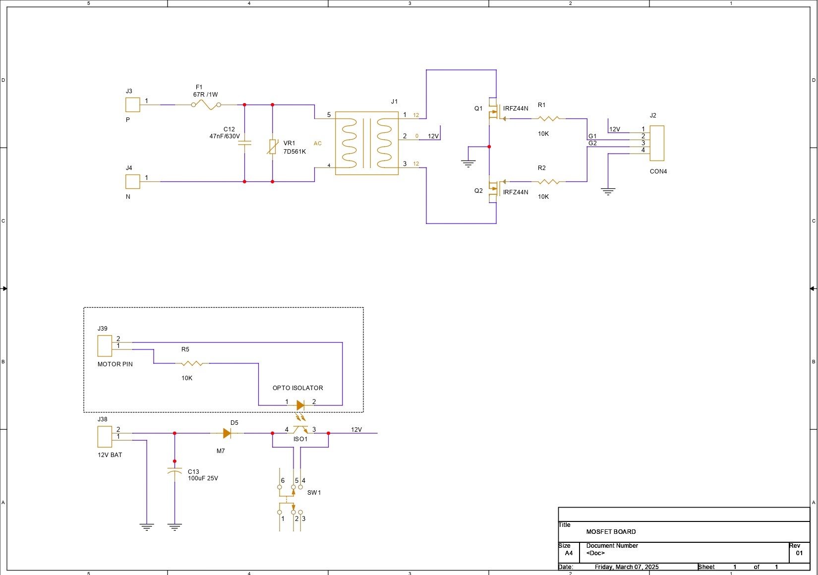
We begin this project by designing the PCB, which consists of two primary sections for modularity.
The CD4047 Driver is the initial section, which consists of the CD4047 IC, a potentiometer, and a load resistor. The CD4047 IC generates square wave pulses, and the frequency can be adjusted using the potentiometer. This provides fine control over the output frequency, which is generally set to 50 Hz or 60 Hz for normal AC applications. The load resistor ensures that the CD4047 IC's output pulses remain stable.
These pulses are then sent into the circuit's second section, the MOSFET BOARD, which includes MOSFETs, a transformer, capacitors, and other essential components.
The MOSFETs amplify the square wave pulses received from the CD driver by turning on and off, enhancing the signal. The amplified signal is then fed into the transformer's primary winding, which increases the voltage to the necessary AC level.
The transformer turns the amplified square wave signal into a higher-voltage AC output. Capacitors are employed to filter the output, resulting in a smooth AC waveform with little noise and ripples. This arrangement simplifies troubleshooting and upgrading while also improving heat management by dispersing components across multiple boards. As a result, the inverter efficiently transforms 12V DC power into a uniform AC voltage, making it suited for a variety of applications that require AC power from a DC source.
This board also has two mounting holes, so the transformer can be securely attached with nuts and bolts to the circuit.
We've also added CON 2 screw terminals, via which we'll connect a 12V lithium battery pack to the circuit.
PCBWAY ServiceWe created two PCBs for this project: the CD4047 driver and the MOSFET board. Two orders were placed, one for the CD4047 driver and one for the MOSFET board.
The CD4047 Driver Board was ordered with black solder mask and white silkscreen, and the MOSFET Board was ordered with yellow solder mask and white silkscreen.
After placing the order, the PCBs were received within a week, and the PCB quality was pretty great.
Their commitment to quality and customer satisfaction has been unwavering, leading to significant growth and expansion.
Also, PCBWAY is organizing a PCB badge-making competition to mark their 11th anniversary, inviting designers and makers to showcase their creativity by designing badges that celebrate the company's legacy and envision a bold future. Participants must incorporate the elements "PCBWay" and the number "11" in their designs and can use PCB, PCB+SMT/THT, or PCB+3D printing techniques. Submissions can be posted in the comments, emailed, or shared on social media with the hashtag #PCBWay11BadgeContest.
Prizes include cash, PCBway coupons, and free prototyping services for all qualifying entries.
You guys can check out PCBWAY If you want great PCB service at an affordable rate.
MOSFET BOARD ASSEMBLY- We begin the Mosfet board assembly procedure by applying solderpaste to each SMD component pad with a solder paste dispenser needle; the solderpaste we use is Sn/PB 63/37.
- Next, we use an EDS tweezer to select and position all of the SMD components.
- We lifted the PCB and placed it on the SMD Reflow hotplate, which heated it from below until it reached the solder paste melting temperature. As soon as the PCB reaches the solder paste melting temperature, the solder paste melts and all components are attached to their pads.
- After soldering all of the SMD components, we begin the THT assembly process, which begins with the installation of all through-hole components such as MOSFETs, resistors, CON4 connectors for driver board placement, CON 2 screw terminals, switch, and so on.
- We next fip the board and solder all of the THT component pads with a soldering iron.
- After we've added all of the through-hole components, we'll add the transformer to complete our board.
- The transformer is first installed, and then two M2.5 nuts and bolts are used to fasten it to the mounting holes on the PCB.
- We next connected the transformer's AC wires to the AC side of the circuit, followed by the DC wires.
The Mosfet -Transformer Board has been completely assembled.
CD4047 DRIVER BOARD- The CD4047 Driver Assembly process begins by applying solderpaste to the SMD capacitor pad. Our driver board includes one SMD component, the 100 nF decoupling capacitor.
- We used a tweezer to pick up and place the SMD capacitor on its pad.
- We used our tiny reflow hotplate from PCBWAY giftshop to solder the capacitor onto the PCB by heating the solder paste to its melting point.
- The through-hole components, which comprise the CD4047 IC itself, an 82 Ohm load resistor, a potentiometer, and a CON4 header pin connector, are all added in their place and then soldered from the bottom side of the PCB using a soldering iron.
- Following assembly verification of both the Mosfet board and the CD4047 driver circuit, we pick the CD4047 driver circuit and connect it to the Mosfet board via both boards' con4 ports.
- We have attached a female header pin to the Mosfet board and a male header pin to the CD4047 board. Using these two connectors, we can join them together as if they were modules.
- Because of this connector, we can later modify or switch the CD4047 for a microcontroller or a better circuit to improve the setup.
As a power supply for our inverter circuit, we use a 12V 5.2Ah Li-ion battery pack made up of six 18650 3.7V 2600mAh Lithium cells coupled in 3S 2P arrangement with a BMS or battery management system.
When fully charged, this pack delivers an output voltage of 12.6V.
TESTINGWe begin the testing process by connecting the battery's VCC and GND terminals to the CON2 screw terminal connector installed on the motherboard.
We connected a multimeter to the transformer's output terminals and set it to read AC voltage.
By pressing the ON/OFF push switch, our device goes on and we get a voltage measurement on our multimeter; we get 208V AC, which can be adjusted using the potentiometer to change the frequency of the CD4047.
LIGHT SOURCEAs for the light source that we will use next, we are utilizing an antique-looking AC 9W bulb that resembles antique filament bulbs, but the one I am using has an LED string inside as well as a driver hidden inside the B22 holder.
We're also utilizing a regular B22 holder to connect our bulb to the AC side of our inverter.
The live and neutral wires from the inverter's AC side are linked to the screw terminals on the B22 holder.
RESULTHere's the finished product of this basic yet efficient build: a functional PowerPulse Inverter that is currently powering a 9W light with a 12V lithium-ion battery pack. The inbuilt ON/OFF switch allows us to easily turn on and off the bulb.
This setup not only exhibits the inverter's efficiency but also its practical applicability in supplying a dependable AC power source from a DC supply. The modular design and robust components assure consistent performance and ease of use, making this inverter a versatile and convenient option for a variety of lighting applications.
WHAT'S NEXT?
The main purpose of constructing this inverter circuit was to build a retro-looking lantern for an upcoming project, and I wanted to utilize an antique-looking LED bulb that runs on AC; therefore, the inverter project was created to power the AC bulb from a DC source.
I will be providing all of the specifics regarding the upcoming lantern project shortly, so stay tuned.
Please let me know if you require any additional assistance; all the documents, files, and code are included in the article.
Thanks for reaching this far, and I will be back with a new project pretty soon.
Peace.

_t9PF3orMPd.png?auto=compress%2Cformat&w=40&h=40&fit=fillmax&bg=fff&dpr=2)


Comments
Please log in or sign up to comment.