Hey everyone what's up!
So here's my 3D Printed Self-balancing robot which is powered by an Arduino nano board and has an MPU6050 to get the accelerometer and gyro readings to balance itself using the PID function.
This robot setup itself is almost 3D Printed except for its big nylon wheels, I bought the wheels from the local hardware store but you can purchase them from the internet.
In this post, I'm gonna show you guys how you can make your own Self-balancing bot in few easy steps with an Arduino board and MPU650.
Materials Required3D Printed Parts-- Base x 1
- Battery Holder x 1
- Bottom x 1
- Bush x 2
- Upper-Level Part (Optional)
- Trolly Nylon wheels 7inch Dia x 2
- Nuts and Bolts as per requirement
- DC Gear Motor x 2
- 12V Battery pack
- Arduino Nano
- Custom PCB
- MPU6050
- L298N Motor Driver
The First step of building this Robot was to prepare a basic body/structure.
- I modeled the Gear DC Motors in Fusion360 and then prepared a base body around the motors which hold both Gear motors.
- then I modeled nylon wheels and made a Bush or coupling to connect the wheel with the motor shaft.
- the bush part that I prepared will be the same for both wheels.
- lithium battery pack goes on top and then it is held in its place by the battery holder part.
- For increasing the height of this robot, I added four threaded rods on the battery holder and then added yet another 3D printed part which is the upper level.
(Fusion360 file along with STL files are provided so you can edit this structure of mine according to your preference)
By adding Rods and connecting the upper-level part, the height of the robot increases and we can add a bunch of stuff to it.
In the end, I 3D Printed all the parts and then assembled the robot.
I used PLA for these but you can use ABS. I used 30% gyroid Infill for these parts.
Next is the electronics wiring!
WiringandElectronics
At the bottom side, I mounted electronics components which include the Arduino board, MPU6050, and the L298N motor driver board.
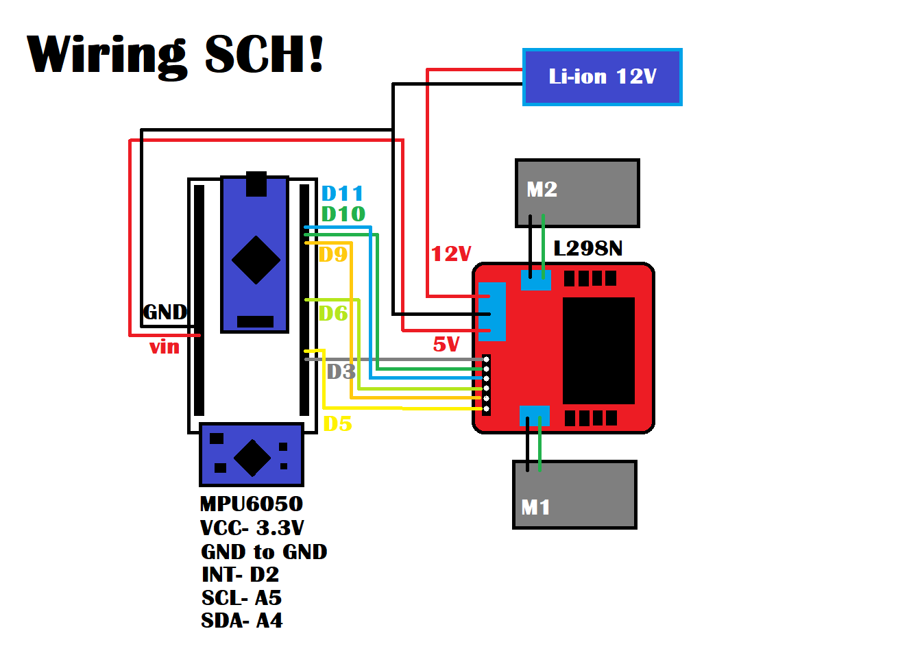
The wiring connection of this project is basically this-
MPU6050 connection with Arduino board
- VCC to 3.3V
- GND to GND
- INT to D2
- SCL to A5
- SDA to D4
L298N Motor Driver connection with Arduino board
- 5V to Vin
- GND to GND
- ENA to D3
- ENB to D5
- IN1 to D10
- IN2 to D11
- IN3 to D6
- IN4 to D9
- 12V to Battery +ve
- GND to Battery -ve
Now let's look at the main components of this project which is the MPU6050.
the MPU is a MEMS-based 6 axis motion tracking device that has an On-chip Gyro and accelerometer sensor along with a temperature sensor. it uses an I2C interface for communication and required operating the voltage between 3.3 to 5V.
MPU6050 uses this library from adafruit - https://github.com/adafruit/Adafruit_MPU6050
For Connecting MPU6050 with Arduino Nano, I used a PCB from an OLD Project which was provided by JLCPCB. You can check them out if you need a great PCB Service for less cost!
I added some wires to connect the PCB with the L298N in the above-mentioned configuration.
L298N is an H bridge motor driver commonly used for making robot projects as it can drive 12V DC Motor with 2A Output Max which is enough for this small project.
PIDPID or Proportional integral derivative is basically a feedback system in which the output is controlled by readings taken and edited by the PID system.
- Proportional control refers to an adjustment that is proportional to how much the error is. Proportional control produces offset in its correction due to disturbances.
- The Integral controller has the ability to remove this offset and bring back the error to zero.
- Derivative control deals with the rate of change of the error. If integral control looks at the history of the error, derivative control predicts the error.
This was PID in Nutshell, now for a practical example, you can check out the PID Library for Arduino which lets you control a bunch of stuff.
https://github.com/br3ttb/Arduino-PID-Library/blob...
Main CodeMain Code for this project is attached above.
Before using this code, you need to download the following libraries-
- MPU6050 library- https://github.com/adafruit/Adafruit_MPU6050
- L motor controller library- https://github.com/lukagabric/Franko/blob/master/l...
- PID Library- https://github.com/br3ttb/Arduino-PID-Library/blob...
I first installed the MPU6050 library and uploaded one of its example sketches which was a plotter sketch.
by moving the robot up/down, the graph changes, this means the MPU6050 is working properly.
Now upload the main code but before uploading, remember to change Motor pinouts according to your connection.
also, after uploading the sketch, your robot might not balance itself properly, so we have to tweak few values which are these
- To increase the stability of the robot, KP will make the robot fall
- KD will increase the oscillation!
by editing these values, your robot will become more stable, but by putting the wrong values, your robot might become more unstable.
anyways, just upload this code to your robot and watch the magic of MPU6050 and PID
RESULThere's the video of this Self-balancing robot-
Further ImprovementsSelf Balancing Part of this robot is working properly but it still requires a lot of changes which includes getting rid of unnecessary movement in the wheel when the motor is at a stationary position, and the height of the Robot can increase by adding the Upper level with threaded rods.
also, an Ultrasonic sensor can be used here to avoid obstacles while balancing.
These are for part 2 so stay tuned for that!
Comment if you guys run into any problem, I'll help you out!


_t9PF3orMPd.png?auto=compress%2Cformat&w=40&h=40&fit=fillmax&bg=fff&dpr=2)


_3u05Tpwasz.png?auto=compress%2Cformat&w=40&h=40&fit=fillmax&bg=fff&dpr=2)

Comments
Please log in or sign up to comment.