

Hardware components | ||||||
 |
| × | 1 | |||
| × | 1 | ||||
 |
| × | 1 | |||
 |
| × | 1 | |||
 |
| × | 1 | |||
| × | 1 | ||||
Software apps and online services | ||||||
| ||||||
| ||||||
Recently I took a course on Udemy about RTOS & learned the features of FreeRTOS. I wanted to run it on my ARM-based board which is a STM32F103C8T6 with an ARM Cortex-M3 processor. I didn't find on the internet a lot of information on how to setup FreeRTOS on this board so I decided to make a tutorial/project which I hope will help other people to start using this OS on such a small board but with many features. This is an easy project, in which I will create two tasks and output strings to the USART to test the functionality of the RTOS.
Tools used- STM32F103C8T6 board
- an USB to USART converter (eg. FTDI breakout board)
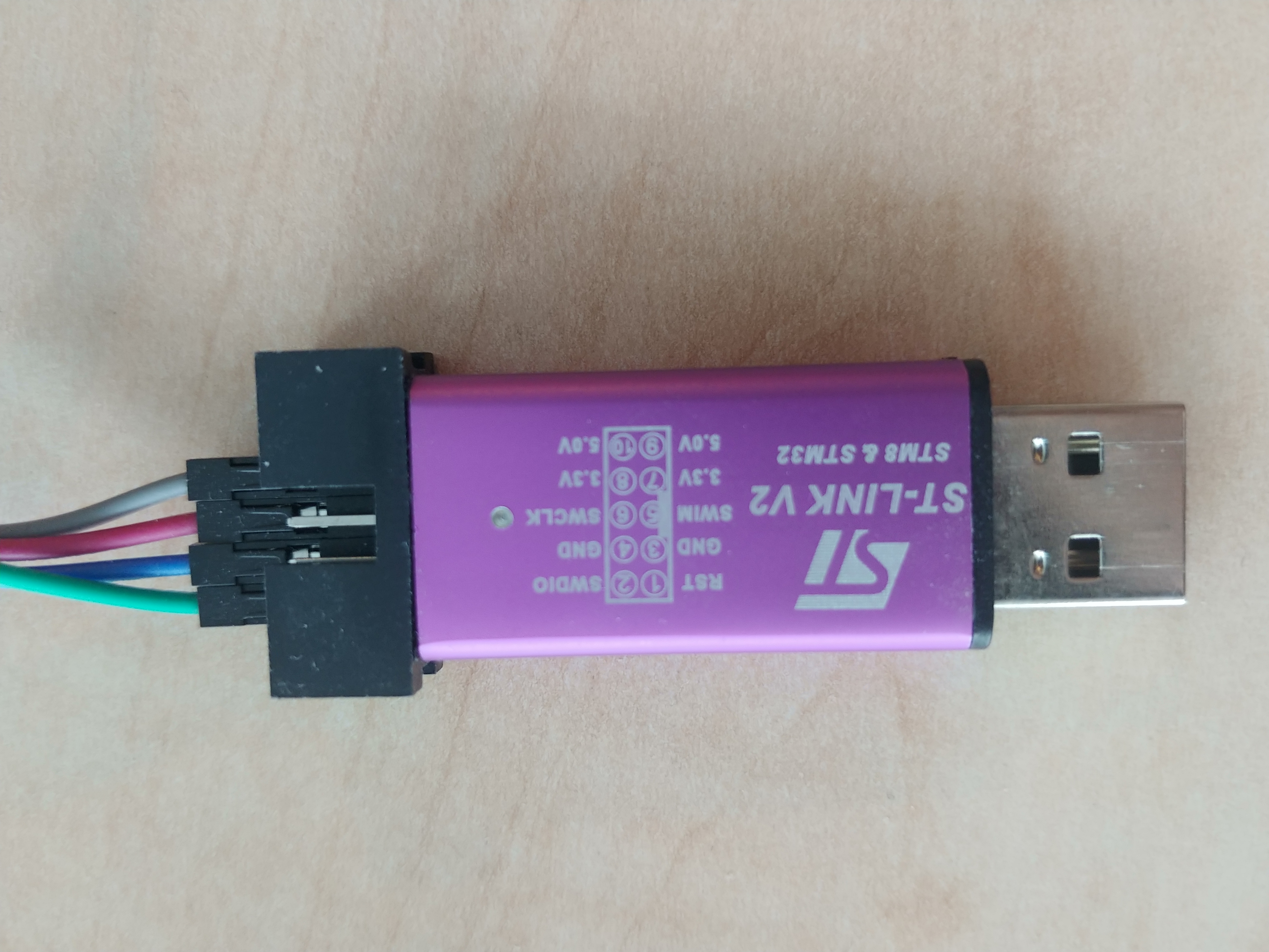
- ST-Link V2 for STM8 & STM32
- Keil uVision software
The IDE can be downloaded from this link from where you should click MDK-Arm which will take you to the download page. You have to fill out a download form. Click the Submit button and download the install executable.
Install it like any other Windows application and you should have a shortcut to the application on your Desktop. Open it and you should get to the same window as the one in the third slide.
Before creating a new project we must install the software packs. Below there are print screens with steps how to do that. Click on the "Pack installer" button, wait for the menu to be loaded.
We will search in the Devices menu for STM32F103C8. On the left side there is listed all the available packages for this micro controller. You need to install the following:
- Keil::STM32F1xx_DFP
- ARM::CMSIS
- ARM::CMSIS-Driver
- ARM::CMSIS-FreeRTOS
- Keil::ARM_Compiler
Close the window when the packages are installed.
To create a new project click on the Project tab -> "New uVision Project". Before naming your project and clicking save I suggest to make a new folder because the IDE doesn't create one. It's better to have all the source files in one place. I named the folder & the project "keil-FreeRTOS".
After this steps we have to select what software packs will be used in the project. If during selection the check boxes you see a warning that some packages are depended of others, click on the "Resolve" button and it will automatically add them to the project.
Below are steps for adding the packages.
OK, now let's get into the code. The first step would be to enable USART1 & set the TX and RX pins. In the RTE_Device.h file, which is found under the Device drop-down icon, search for this lines and change this macros.
// <e> USART1 (Universal synchronous asynchronous receiver transmitter)
// <i> Configuration settings for Driver_USART1 in component ::CMSIS Driver:USART
#define RTE_USART1                      1       // change this macro to 1
//   <o> USART1_TX Pin <0=>Not Used <1=>PA9
#define RTE_USART1_TX_PORT_ID_DEF       1       // change this macro to 1
#if    (RTE_USART1_TX_PORT_ID_DEF == 0)
#define RTE_USART1_TX_DEF               0
#elif  (RTE_USART1_TX_PORT_ID_DEF == 1)
#define RTE_USART1_TX_DEF               1
#define RTE_USART1_TX_PORT_DEF          GPIOA
#define RTE_USART1_TX_BIT_DEF           9
#else
#error "Invalid USART1_TX Pin Configuration!"
#endif
//   <o> USART1_RX Pin <0=>Not Used <1=>PA10
#define RTE_USART1_RX_PORT_ID_DEF       1      // change this macro to 1
#if    (RTE_USART1_RX_PORT_ID_DEF == 0)
#define RTE_USART1_RX_DEF               0
#elif  (RTE_USART1_RX_PORT_ID_DEF == 1)
#define RTE_USART1_RX_DEF               1
#define RTE_USART1_RX_PORT_DEF          GPIOA
#define RTE_USART1_RX_BIT_DEF           10
#else
#error "Invalid USART1_RX Pin Configuration!"
#endif
In this configuration pin PA9 will be TX and pin PA10 will be RX.
For redirecting printf() to USART, Keil provides a User Code Template file. This is a generated file that redirects the output to the USART driver to send it out the pins that we configured earlier. Below are the steps.
In this folder we will specify to which USART we will output and configure the baud rate.
// <h>STDOUT USART Interface
//   <o>Connect to hardware via Driver_USART# <0-255>
//   <i>Select driver control block for USART interface
#define USART_DRV_NUM           1        // this macro defines the USART used. In our                                          // case USART1
//   <o>Baudrate
#define USART_BAUDRATE          115200   // Change the baud rate to 115200
// </h>
Now let's add our main.c file where we will initialize the micro controller, create some tasks and output a string with the task name when they are running. For adding a file the procedure is the same as described above.
Note: The extension of the file has to be added, the tool doesn't add the extension.
Code in main.c/* Include files */
#include <stdio.h>
#include <stdlib.h>
#include "FreeRTOS.h"
#include "task.h"
#include "semphr.h"
/* The task functions prototype*/
void vTask1( void *pvParameters );
void vTask2( void *pvParameters );
/* Task parameter to be sent to the task function */
const char *pvTask1 = "Task1 is running.";
const char *pvTask2 = "Task2 is running.";
/* Extern functions */
extern void SystemInit(void);
extern void SystemCoreClockUpdate(void);
extern int stdout_init (void);
/*-----------------------------------------------------------*/
/* Global semaphore variable */
SemaphoreHandle_t xSemaphore = NULL;
int main( void )
{
/* Board initializations */
SystemInit();
/* This function initializes the MCU clock, PLL will be used to generate Main MCU clock */
SystemCoreClockUpdate();
/* Initialize the serial I/O(console ), making standard output to be send to USART1 */
stdout_init();
printf("Initialization is done.\r\n");
/* Create one of the two tasks. */
xTaskCreate(vTask1, /* Pointer to the function that implements the task. */
"Task 1", /* Text name for the task. This is to facilitate debugging only. */
configMINIMAL_STACK_SIZE, /* Stack depth in words. */
(void*)pvTask1, /* We are not using the task parameter. */
1, /* This task will run at priority 1. */
NULL ); /* We are not using the task handle. */
/* Create the other task in exactly the same way. */
xTaskCreate( vTask2, "Task 2", configMINIMAL_STACK_SIZE, (void*)pvTask2, 1, NULL );
/* Create a binary semaphore */
xSemaphore = xSemaphoreCreateBinary();
/* make the semaphore token available for the first time */
xSemaphoreGive( xSemaphore);
/* Start the scheduler so our tasks start executing. */
vTaskStartScheduler();
/* If all is well we will never reach here as the scheduler will now be
running. If we do reach here then it is likely that there was insufficient
heap available for the idle task to be created. */
for( ;; );
}
/*-----------------------------------------------------------*/
void vTask1( void *pvParameters )
{
char *pcTaskName = (char *) pvParameters;
/* Task is implemented in an infinite loop. */
for( ;; )
{
/* Take semaphore */
xSemaphoreTake(xSemaphore,(TickType_t) portMAX_DELAY);
/* Print out the name of this task. */
printf( "%s\r\n",pcTaskName );
/* Give semaphore */
xSemaphoreGive(xSemaphore);
/* Delay for a period. */
vTaskDelay( 2000 / portTICK_PERIOD_MS );
}
}
/*-----------------------------------------------------------*/
void vTask2( void *pvParameters )
{
char *pcTaskName = (char *) pvParameters;
/* Task is implemented in an infinite loop. */
for( ;; )
{
/* Take semaphore */
xSemaphoreTake(xSemaphore,(TickType_t) portMAX_DELAY);
/* Print out the name of this task. */
printf( "%s\r\n",pcTaskName );
/* Give semaphore */
xSemaphoreGive(xSemaphore);
/* Delay for a period. */
vTaskDelay( 2000 / portTICK_PERIOD_MS );
}
}
In main the following are happening:
- the micro controller is initialized using SystemInit(), the clock is set using SystemCoreClockUpdate() & stdout_init() intialize USART1.
- 2 tasks are created and a binary semaphore
- the FreeRTOS task scheduler is started
The 2 tasks will run with the same priority so they will have equal execution time. The binary semaphore is used to prevent the 2 tasks to race for outputting their corresponding strings at the same time.
When task 1 will be in the "Running" state it will take the semaphore, use printf() and give the semaphore back to be used by another task. If task 2 will try to take the semaphore while is used by task 1, it will get in the "Blocked" state and wait for the semaphore to be available.
The delay in the tasks is for ease of following the output. Otherwise it would have outputted continuously.
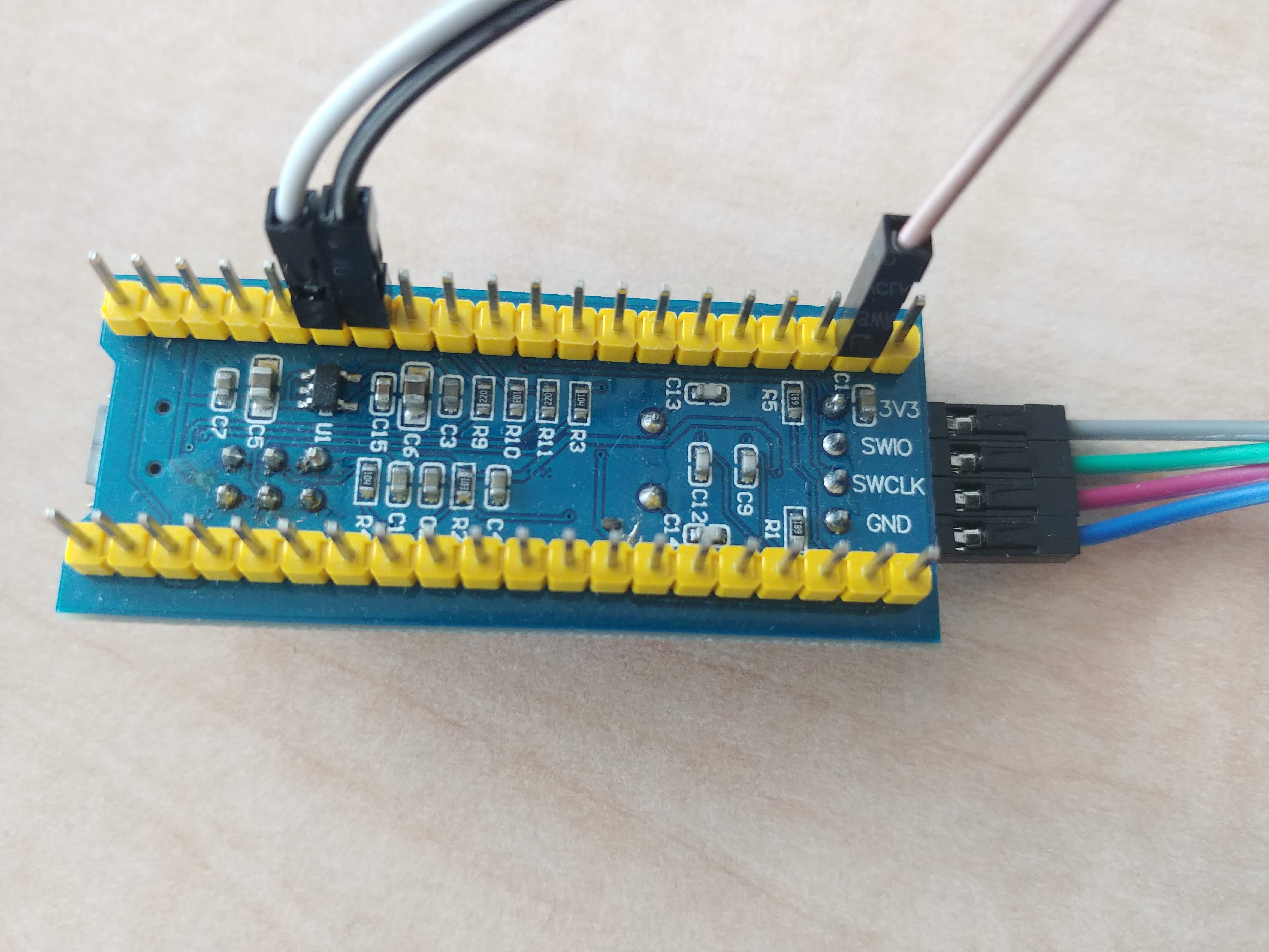
ConnectionsI attached below pictures with the SW pins of the ST-Link V2 & STM32F103C8T6. You have to connect them using jumper wires to their corresponding one. In the Fritzing diagram you can see how to connect the FTDI breakout board to the micro controller.
Before flashing you have to set the debugger used.
Press F7 which is the shortcut for "Build" and if it doesn't have any errors, press F8 to download the code on the board.
Open a terminal application( I'm using Putty) check on what COM port the FTDI board communicates on and set the baud rate to be same as the one on the board. The output should be as the one below. You can press the reset button to initiliaze the board and start the RTOS again.
I find freeRTOS to be an easy to understand and use RTOS for a beginner. The Keil IDE provides a lot of help for creating applications using the OS features. I will continue with other projects in which I will cover more features of this RTOS and the STM32F103C8T6.
For ease I attached the entire project as a zip file.

_3u05Tpwasz.png?auto=compress%2Cformat&w=40&h=40&fit=fillmax&bg=fff&dpr=2)

Comments