Want to be a desperate T-Rex who's ready to explore the wondrous 2-D, 8-bit, binary colored world of Google Chrome with joy and excitement ? So make sure you exercise your knees daily to keep up with the high scores.
This project won the Best Hardware Hack presented by Digi-Key category prize in the Who Wants to be Hackionaire hackathon organized by MLH
Step One: PartsI've used CircuitPython to program the Seeeduino Xiao but it's also compatible with Arduino. You can choose any ATSAMD21 microcontroller board that supports CircuitPython to follow along this project. I chose Xiao because of it's miniscule size, suitable for wearable projects.
Note: For general I/O pins: Working voltage of MCU is 3.3V. Voltage input connected to general I/O pins may cause chip damage if it’ higher than 3.3V.
For power supply pins: The built-in DC-DC converter circuit able to change 5V voltage into 3.3V allows to power the device with a 5V supply via VIN-PIN and 5V-PIN.
The Adafruit LIS3DH is a triple-axis accelerometer whose library supports both I2C and SPI but we'll be using SPI interface in this project. A newer version of this board is available which is black in color and has STEMMA QT connectors or the SparkFun Qwiic I2C connectors on either side.
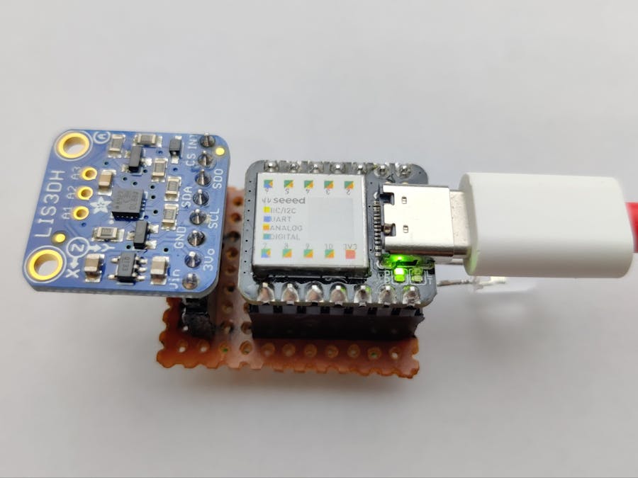
I made my project on breadboard initially then I soldered on female headers on a PCB to improve the form factor. You can, if you want, solder the board directly as it has castellated pins and wouldn't stand out much.
Step Two: ConceptSo this project consists of mainly 3 sections:
- Sensor (LIS3DH Accelerometer)
- Logic Unit (ATSAMD21)
- Output Unit (LEDs and Keyboard)
The accelerometer used to detect the changes in acceleration of the person due to the movement. When a person jumps up or ducks down, he/she produce a relative acceleration to do so. We measure the change in acceleration by taking the absolute value of X, Y and Z axes because the change would be positive no matter we are going up or down.
The output unit of the project send the command to press the UP arrow key and turns on the red LED for 500 milliseconds. Similarly, if it detects a duck, the board presses the DOWN arrow key and turns on the blue LED for 500 milliseconds. I've put some print statements in between but it's only for debugging purposes and can be ignored. Since Seeeduino Xiao does not support Mu's Serial console as of this writing, you can use an application like PuTTY or Arduino's Serial Monitor to see the values of X, Y and Z axes.
# code.py
"""
Project Name: Jump Yo' Rex
Author: Advik Singhania
Created On: 28th November, 2020; 07:48 PM IST

Make sure to copy the adafruit_hid library folder and
adafruit_lis3dh to the /lib folder of your CIRCUITPY drive.
I've connected a red LED to pin D4 to indicate jumps and
a blue LED to pin D0 to indicate ducks.
This source code has been tested for Seeeduino Xiao and can also work on CircuitPython supported boards.
"""

import time
import board
import digitalio
import busio
import adafruit_lis3dh
import usb_hid
from adafruit_hid.keyboard import Keyboard
from adafruit_hid.keyboard_layout_us import KeyboardLayoutUS
from adafruit_hid.keycode import Keycode

# Configurnig pins for the SPI connection:
spi = busio.SPI(board.SCK, board.MOSI, board.MISO)
cs = digitalio.DigitalInOut(board.D5)  # Set to appropriate CS pin!
int1 = digitalio.DigitalInOut(board.D6)  # Set to correct pin for interrupt!
lis3dh = adafruit_lis3dh.LIS3DH_SPI(spi, cs, int1=int1)

# Initializing Keyboard:
keyboard = Keyboard(usb_hid.devices)
keyboard_layout = KeyboardLayoutUS(keyboard)

time.sleep(1)

# Setting up LEDs for Jump(ledj) and Duck(ledd)
ledj = digitalio.DigitalInOut(board.D4)
ledj.direction = digitalio.Direction.OUTPUT
ledd = digitalio.DigitalInOut(board.D0)
ledd.direction = digitalio.Direction.OUTPUT

# Printing is for debugging, you can comment the print statements if you want.
print("Waiting for action...")
while True:
    ledj.value = False  # Turning Off LEDs
    ledd.value = False

    x, y, z = lis3dh.acceleration  # Getting values for the acceleration in x, y and z axes
    x, y, z = abs(x), abs(y), abs(z)  # Taking the absolute of the values since the change in relative acceleration will always be positive
    # print(x, y, z)

    # Setting up default position:
    if 8 < x < 10:
        pos = x
    elif 8 < z < 10:
        pos = z
    else:
        pos = y

    # Detecting jumps and ducks:
    if pos > 11:  # You can change these values according to your sensitivity
        print(x, y, z)
        keyboard.press(Keycode.UP_ARROW)  # "Press"...
        keyboard.release_all()
        print('Jumped')
        ledj.value = True
        time.sleep(0.5)
    elif pos < 8:  # You can change these values according to your sensitivity
        print(x, y, z)
        keyboard.press(Keycode.DOWN_ARROW)  # "Press"...
        print('Ducked')
        ledd.value = True
        time.sleep(0.5)
        keyboard.release_all()
        time.sleep(0.5)

    time.sleep(0.05)
In the source code, we first import the necessary standard libraries like time, board, digitalio which are built-in the board. Then to use the other hardware, we add the adafruit_bus_device, adafruit_hid and adafruit_lis3dh libraries, manually in order for the functions to work. We're using the Serial Peripheral Interface (SPI) connection to communicate between the accelerometer and the microcontroller board, so I setup the pin configurations for that.
Then we initialize what kind of Keyboard we'll be using which is US-American standard layout. There's a delay of 1 second so that it gets ready before the program starts further execution. ledj (red LED) is used to indicate when a jump has occurred, whereas ledd (blue LED) is used to indicate when a duck has occurred.
The main while loop consists of all the logic that needs to run continuously. The board checks what the default position is by checking which axis has the value in the range of gravitational constant (g ~ 9.8 m/s²). Then it calculates if the change in acceleration is greater than 10 (roughly g). At this point, it is up to you to see and calibrate the values in if conditions as per your requirement. If the pos value is greater than 11, it executes a jump(up arrow and red led) and if it is less than 8, it executes a duck(down arrow and blue led).
Get started with CircuitPython if you haven't already. You'll need to install Mu (preferred editor for CircuitPython) on your PC and make sure that you're running the latest version of CircuitPython on the board you're using. More info can be found here,there and everywhere.
Now after downloading the code.py and lib.zip from the GitHub repo, extract the lib.zip and copy the lib folder in your CIRCUITPY drive of the board. Disconnect from the Internet and open Google Chrome T-Rex game.
Now copy the code.py in your drive's parent directory.
NOTE: The code will start executing as soon as you copy the code.py in your CIRCUITPY drive, so close the windows that you think are important or they might get corrupted. As the project would take control over the Up and Down arrow keys.Step Four: Wiring
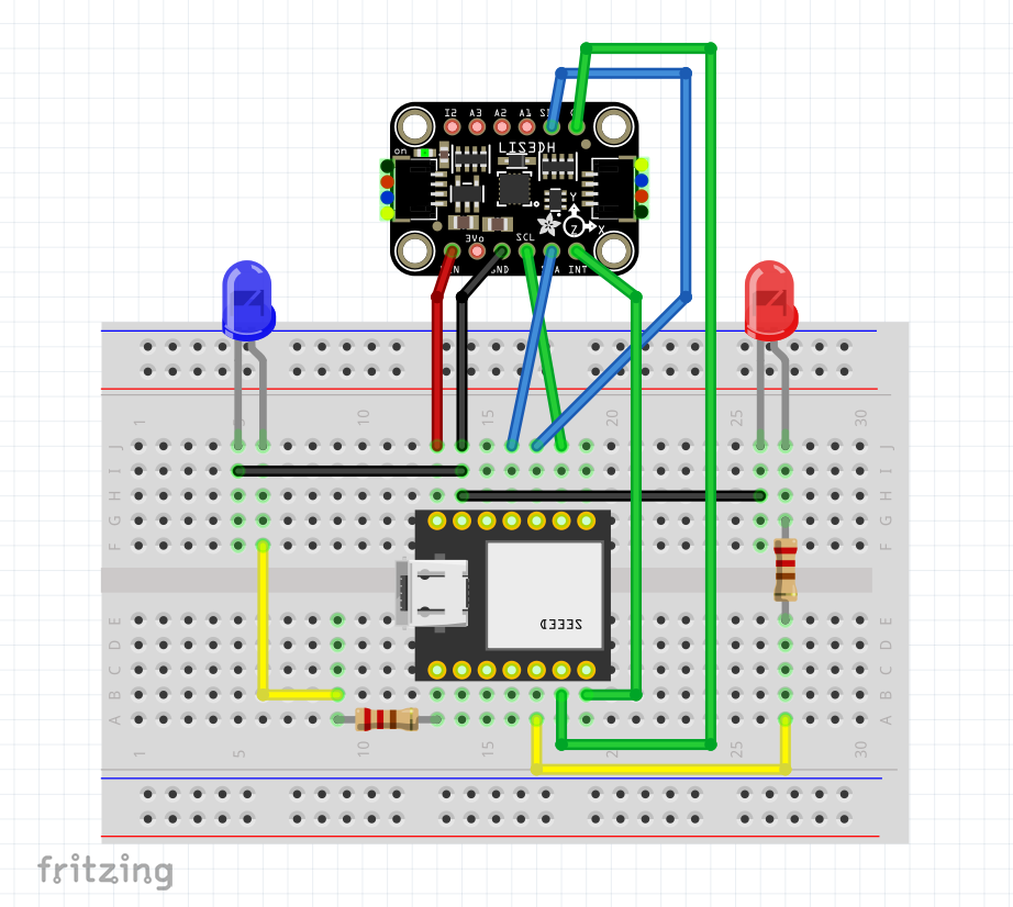
After uploading the code, disconnect the board and wire the components on a breadboard as shown above. The connections are pretty simple between the Xiao and LIS3DH:
- Board 3V to sensor Vin
- Board GND to sensor GND
- Board SCK to sensor SCL
- Board MOSI to sensor SDA
- Board MISO to sensor SDO
- Board D5 to sensor CS
- Board D6 to sensor INT
Connect the positive lead of the red LED (ledj) to pin D4 via a 220 ohm resistor, and the positive lead of the blue LED (ledd) to pin D0 via a 220 ohm resistor. Connect the ground leads of the LEDs to the common GND.
And you're done!
You can wear this device on or above your waist so that the T-Rex shadows your movements. You can also solder the components on a general purpose PCB to improve the form factor as I did and make a case for it. This project still uses a USB cable to power and interact with the computer, so I'm planning to use Bluetooth instead and will try to improve the interaction overtime. Pretty soon the T-Rex within will be free from the leash and roam around jumping and going crazy.
Thanking you for taking interest in this project. Feel free to comment below your feedback and ask your doubts if any. I will try and answer as much as possible.


_3u05Tpwasz.png?auto=compress%2Cformat&w=40&h=40&fit=fillmax&bg=fff&dpr=2)
Comments
Please log in or sign up to comment.