The small size and low cost of #PocketBeagle from BeagleBoard.org inspired us to tech-out our Halloween Pumpkin this year. Techniques in this project can be used for any multi-LED project. Design your own!
While this 1GHz Linux PC has the performance and peripheral access to support much larger projects, we like starting with LEDs for a fun way to learn a new platform. We hope you enjoy tech-ing out your own Pumpkin or other art shape!
We wanted to do something more than a single LED blinky. We decided to make a sketch of BeagleBoard.org mascot named Boris on a pumpkin and then light it up with LEDs.
Things can get messy with a real pumpkin so an artificial pumpkin with readily available 5mm red LEDs (2V, 20mA, clear lens) on it felt like a good idea.
We began by printing out the beagleboard.org Boris the beagle mascot picture and sticking it on our pumpkin. This helped us figure out the outline for LED placement. An LED every inch along the outline of the mascot would look good. So we marked the points where LEDs need to be placed and started making holes using an ice pick. (By the way, Cathy is an expert when it comes to ice picks!)
We wanted to have control over different parts of the Beagle like eyes, ears, tail etc so the LEDs were divided into 7 sets (Ear, Head, Eyes, Tongue, Tail in Up position, Tail in Down position and Legs). The LEDs were connected in parallel. All the LEDs would share a common anode but cathode is different for different sets so that we can turn on / off one or more sets as we like using PocketBeagle.
Soldering the LEDs together helped us achieve decent structural strength (just enough strength for this project).
Soldering all the LEDs together took some time. Once done, all the LEDs were placed into the pumpkin holes suitably.
For this project, we have used 71 LEDs in total. They are divided into different sections as follows:
- Ear - 10 LEDs
- Head - 16 LEDs
- Eye - 4 LEDs
- Tongue - 3 LEDs
- Tail up position - 4 LEDs
- Tail down position - 4 LEDs
- Leg - 30 LEDs
(You can use different number of LEDs to suit your own sketch/project)
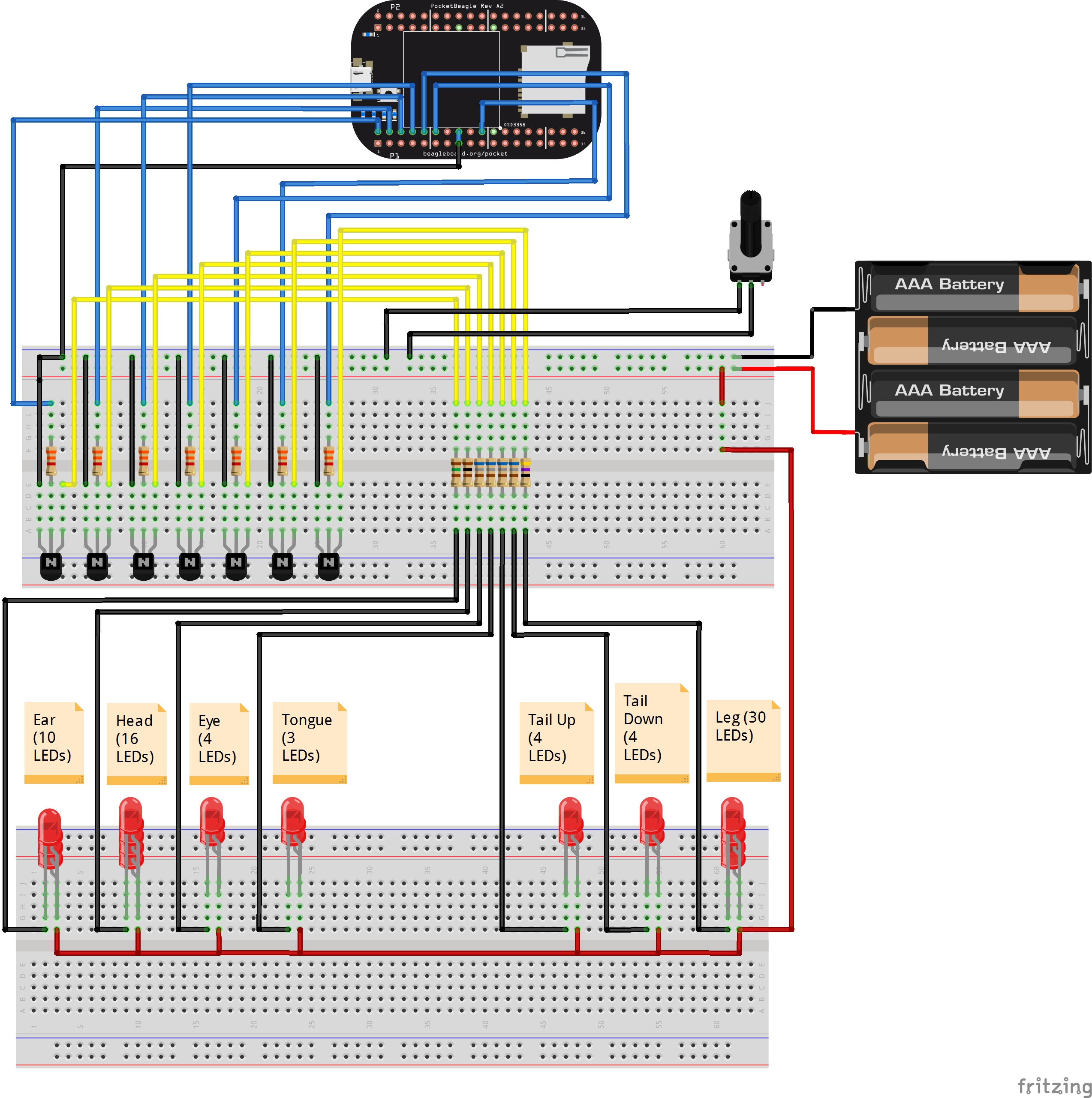
A control circuit consisting of PocketBeagle, BC548 NPN transistors, resistors and linear potentiometer was put together on a breadboard and was suitably connected to our LED array to bring the beagle sketch to life!
The GPIOs of PocketBeagle can handle approx. 3mA of current but our array of LEDs required much more than that. More the number of LEDs in the array, higher will be the current requirement. Current consumption also increases with increase in brightness of the LEDs. Therefore, we used BC548 transistors (in switching mode) to act as buffer between PocketBeagle and LED array. These transistors can tolerate continuous collector current of up to 100mA. A potentiometer was also used to adjust brightness of the LED array. The breadboard circuit was powered using 4.8V battery pack (4 AA or 4 AAA batteries). PocketBeagle was powered through its Micro USB B port.
The Fritzing breadboard view of the circuit is given below.
(Make sure LED array resistor values are chosen appropriately if you plan to use different number of LEDs / different type of LEDs for your project. The LEDs may look very dull or may burn out if resistor values are not chosen properly)
The code to manage PocketBeagle GPIO is written in Python using Adafruit BeagleBone Black GPIO library. The code is available below.


Comments
Please log in or sign up to comment.