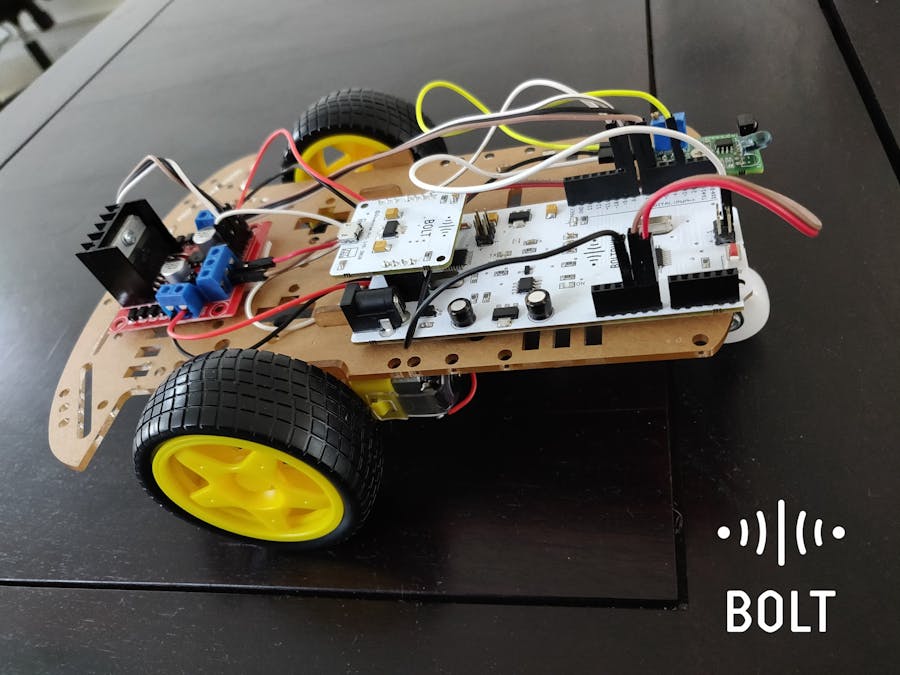
No electronics were damaged while making of this project.
Act One: One fine day...We were working since the morning and had a lot of documentation and code testing remaining on our hands and we desperately needed a break but, playing foosball was not Ideal as it would kick us out of the zone. So to maintain our composure we started thinking of what we could do that would relax us but, still would keep us in that "zone of work". That's when our manager suggested "Why don't you make a little project and put it up on Hackster?". Well good call Pranav.
So we decided to make an Internet controlled -wait-for-it- RC Robot with a tiny little bonus feature (that we will reveal later because suspense is important).
Alright so we were pumped up and we rushed to the in-house hardware shop.
Act Two: The Forest of HardwareWe arrive at the hardware shop, it's filled with kits and components that make your eyes gleam with greed, you hands will be pulled towards them and before you know it you will be soldering parts to make an 8-bit Calculator but, we were focused and didn't let these distractions compel us and we just grabbed what we needed (so should you)
1. Bolt Wifi Module
2. Basic Robotic Kit
3. Arduino UNO or Boltduino
4. L298N Motor driver shield
5. Proximity Sensor
6. Jumper Wires
7. Power Adapter
We safely came back from the Forest of Hardware with all the parts that we needed. It was time for Devashish the Highlord of Hardwarey to work his magic and put together this little Robot.
Here's how he did this.
Assembling the hardware1. Attach the caster wheel in the front middle portion of the chassis as shown.
2. Assemble the robotic car chassis and attach the two DC motors using the nuts and bolts along with the wheels provided as shown.
NOTE: Solder the wires to the motor's terminal before attaching it to chassis.
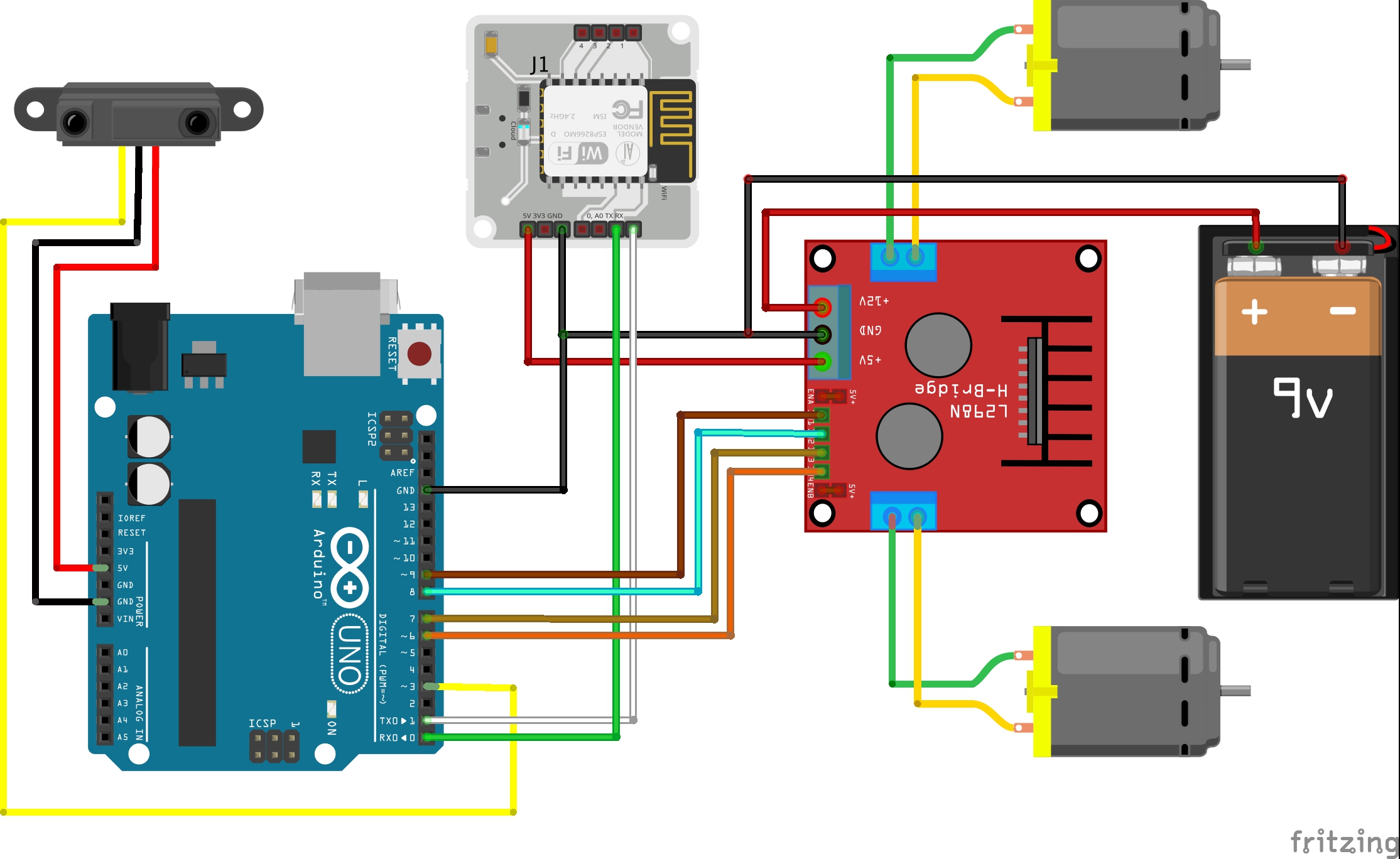
3. Now connect the terminals of the motor to the L298N motor driver module as shown below.
NOTE: Connect both the terminal of the motor on the same side of the driver module.
4. Connect the 5V pin and GND pin of the driver module to 5V and GND of Arduino respectively.
5. Connect the pins 5V, GND, Tx and Rx of Bolt to the pins 5V, GND, Rx and Tx of Arduino respectively. For Boltduino, attach the Bolt unit in the slot present.
6. Connect the four input terminals (IN1, IN2, IN3, IN4) to pins 6, 7, 8 and 9 respectively.
7. Connect the 5V, GND and OUT pins of proximity sensor to pins 5V, GND and 3 of Arduino respectively.
NOTE: For any further help look the schematics given below.
Connecting Bolt to cloud
After assembling the hardware, register and connect the Bolt unit to the Bolt Cloud. Know more at registering and connecting bolt to cloud.
Act Four: And Then There Was ConnectivityNow the Highlord of Hardwarey sent for the Assassin of Kiln of Code (i.e me).
He was tasked to bring this robot to life with his code and connect it to the Cloud. Follow in his footsteps to get your robot working as well.
Step 1: Get the code.
Get the code from the Github repository of this project. Download a.zip file or clone it to your system, what ever suits you.
Step 2: Working with the code.
There are two parts of code:
- A folder named app
- Inside this folder there are two files i. controller.html ii. controller.js. We will talk about them later.
- Then there is the firmware for your Arduino in a file named Bolt_Robot_Car.ino. This will be flashed/uploaded on your Arduino.
Step 3: Setting up Arduino.
Once you are done with setting up your hardware and connecting your bolt to the cloud, upload the firmware present in the file Bolt_Robot_Car.ino to your Arduino. To know how to set up Arduino IDE and upload a code to Arduino follow this link.
Step 4: The Controller App.
Double click on the controller.html file and you should be presented with the following web page.
Now enter your API Key and Device ID into their respective fields, and hit SUBMIT. You can get your API Key and Device ID from your Bolt Cloud Dashboard.
After this you can use the control buttons to control the motion of your robot. The button presses trigger specific JavaScript functions (check file controller.js) to send commands to the Bolt Cloud and then to your Bolt WiFi Module. Now you have an RC bot do what you will with it. There can be multiple things done with this, you can attach a few sensors to it or make it automatic or whatever you wish. And if you mess up don't worry, we the natives of the Maker Land are here to help you anytime.
Act Five: Easter EggsI know a few of you might be thinking "Hey, you said there was a bonus feature, where is it ?" well don't worry we are not gonna leave you high and dry but, there is high chance that you might have already noticed the feature in ActThree:Forging if you haven't, have a look at it again. But, well who has that kind of time so TL;DR your robot will automatically stop if it encounters an obstacle or a blockage in it's path so that you don't end up smashing it up against the wall. Alright that's the end of this tale, take a look at this video to checkout the video tutorial for this project.
Demo:


_ztBMuBhMHo.jpg?auto=compress%2Cformat&w=48&h=48&fit=fill&bg=ffffff)


_3u05Tpwasz.png?auto=compress%2Cformat&w=40&h=40&fit=fillmax&bg=fff&dpr=2)
Comments
Please log in or sign up to comment.