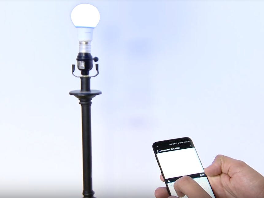
Necessity is the mother of invention... and in this case, the necessity was that I really didn't want to have to get up to turn off my lamp.
I could spend upwards of $100 dollars for an all in one premade solution, or I could expend some elbow grease and make something myself.
Be mindful that this tutorial involves working with high voltage live wires. Proceed with caution.
So we need three main components to take a regular old house lamp into something that is wirelessly controllable.
- A relay: This is how we will control the flow of power to our lamp.
- A wireless module: We need some way to remotely trigger our lamp and I find staying in the same Microchip ecosystem as the path of least resistance.
- A development board: The brains behind the operation, the microcontroller on this thing will trigger both modules and handle any data processing required.
In the hopes of keeping everything simple and in one ecosystem I ended up choosing the PIC16F18875 Curiosity HPC as my dev board. To program this Curiosity board we use a program called MPLAB X, this IDE has a plug in called MCC that contains libraries for a number of sensor boards, including the Relay Click and Bluetooth Click from MikroElektronika.
This board has two sockets that each support the MikroBUS footprint, each one can neatly hold a click from MikroElektronika which lets us keep things neat.
With our hardware assembled we can move onto
Wire StrippersI recommend having some wire strippers handy for cutting the power cord of your chosen lamp. Make sure not to leave excess exposed conduit as you are dealing with live wires.
Step 1 - Create a New Project
Create a new "Stand-Alone" project in MPLAB® Xpress for a PIC16F18875 using the Curiosity HPC board. If you are not sure how to do this, check out the tutorial here.
Step 2 - Open MCC
Open the MPLAB® Code Configurator using the blue shield link on the toolbar. You can find information on how to open MCC here.
Step 3 - Set up the Bluetooth Click
Thanks to MCC the set up is easy, You can find a step by step example here. You will at least need to follow up to step 3 for the purposes of this tutorial.
Step 4 - Setting up the Relay Click
Once again MCC makes this as easy as a few clicks.
Adding Relay ClickUnderneath Device Resources, scroll to the bottom of the menu to find and click Mikro-E Clicks. From there find the Miscellaneous drop down and simply click on the "Relay" option.
In the Pin Manager section select what pins correspond to the RL1 and RL2 printed on the Relay click. For this example RL1 and RL2 correspond to RC2 and RA3 respectively.
From there just generate the code by clicking on the Generate button within MCC.
Step 5 - The Code
Thankfully we are able to use most of the code from the Bluetooth example in our application, for starters copy the highlighted code from EXAMPLE_Bluetooth.c and paste it above your while(1) loop in main.c.
From there we will copy what is inside the while(1) loop within EXAMPLE_Bluetooth.c and drop it within the while(1) of our main.c file.
The only changes necessary to the example are removing the BT_SendData(data, I + 1); from the if statement and replacing it with the triggers fro the relay.
Step 6 - Testing
From there just connect your preferred Bluetooth terminal to the Bluetooth Click, minding any security you may have set for your device, and enjoy your newly IoT-ified lamp!


Comments