As modern day strives to develop sustainable solutions, some of them pose serious challenges. One such challenge is the integrity of battery circuits in electric vehicles. We have recently read news regarding batteries catching fire in electric vehicles. This causes serious collateral damage to man and property. These frequent mishaps have led to consider the safety of lithium batteries very seriously, Even though battery fires typically take time to achieve the heat necessary to start a fire, it is very hard to predict or foresee a potential fire as these battery packs are fully isolated and are not easily exposed for inspection. Short circuits can also happen if the internal circuitry is subjected to high wear and tear or exposed in conditions such as flood, causing a spike in current which can start a fire and damage the whole system.
My team is proposing a potential solution using Infenion CoolMOS Gold super-junction MOSFETs to completely eliminate the intensity of damage caused by such battery fire mishaps. Large amount of research is currently carried out for producing new materials that might not only make batteries lighter and more efficient, but could possibly make them safer. We're still at the early stages of understanding how to make batteries such as lithium ion safer. This project, its findings and future upgrades have a very crucial role in making the modern EV cars, it'spassengers and the fellow pedestrians safer from yet another fateful incident.
Existing solutions only controls the excess charging of batteries in electric vehicles. Our solution not only protects the battery and other residing systems from overcharging, but also from battery fires, battery expansion, temperature rise, short circuits and subsequent damages to other subsidiary components. In addition to that, the system constantly monitors the battery to give warnings and other necessary information to the user.
Keywords: Automotive safety, CoolMOS, MOSFET, Embedded systems
-----------------------------------------------------------------------------------------------------------------
Project Goals:- Battery temperature, expansion and overcharge monitoring
- Engine power cut-off if anomaly detected
- Activate suppression system if anomaly detected
- Overcharge power supply cut-off
- Short circuit cut-off
- Display and warnings
-----------------------------------------------------------------------------------------------------------------
Workflow and Explanation:This project guide explains all the basic steps and procedures that are performed towards attaining the final goals of the project. I will try to keep this as simple as possible so that anyone referring to this guide would be able to infer and understand the concept. Also please keep in mind that I would like to keep this guide as compact as possible for the sake of readability. So, wherever applicable, I will be referring to resources in other websites where detailed information can be obtained instead of repeating everything here. However, the most important points will be mentioned.
The most commonly used battery packs in Electric vehicles are Li-ion battery packs @ 12V spanning to 230V. In this project, we take the case of 12V for avoiding the over-complexity of the design, even though the same can be improved and extended for higher voltages and power. The CoolMOS C7 MOSFET is capable of handling the high energy density requirement in EV cars for fastintervention time and switching frequency, lowmaintenance, smallerfootprint and increasedsafety.
The battery packs can catch fire in two ways. Either being exposed to a fire or through a thermal runaway in the battery itself, caused due to a manufacturing defect or physical damage. When a Lithium Ion battery has a thermal runaway, physical expansion of the battery occurs and electrical shorts within the battery occurs. The energy stored in the battery is released, often violently. This release of energy can cause adjacent battery cells to catch fire or thermally runaway as well. Incorrect usage of batteries such as excessive vibration, elevated heat and charging below freezing can also lead to adverse effects. If a Li-ion battery overheats, hisses or bulges, immediately move the device away from flammable materials and place it on a non-combustible surface. If possible, remove the battery and put it outdoors to burn out. Simply disconnecting the battery from the system may not stop its destructive path.
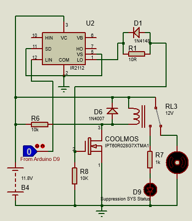
Our solution works by continuously monitoring the expansion and temperature of the Lithium battery packs in electric vehicles by an automatic cutoff unit controlled by an Arduino unit. If the control unit senses excess temperature or expansion of the battery, it cuts off the power from the battery to the motors via a switch and triggers the suppression system, releasing fire suppressant that will eliminate any battery fire or burst from happening. The switches use CoolMOS super junction MOSFETs. The Suppression system can be reused by replacing or refilling the canister. In the event a battery overcharge is sensed by the overcharge protection circuit, charging power to the batteries are cut off from source using the CoolMOS super junction MOSFET switch. This battery protection circuit prevents the overcharge of the battery. Sufficient warnings and information will also be provided to the user.
CoolMOS™ C7 Gold super-junction MOSFET series (G7) brings together the benefits of the improved 600V CoolMOS™ C7 Gold technology, 4 pin Kelvin source capability and the improved thermal properties of the TO-Leadless (TOLL) package to enable a possible SMD solution for high current hard switching topologies such as power factor correction (PFC) up to 3 Kw and for resonant circuits such as high end LLC.
For driving the C7 mosfet, use any compatible EiceDRIVER MOSFET driver such as an IR2112 600 V Driver IC or EiceDRIVER from Infineon technologies.
-----------------------------------------------------------------------------------------------------------------
This project is divided into three main sections: Battery Overcharge Protection Circuit, Battery Health Monitoring Circuit and Suppression System.
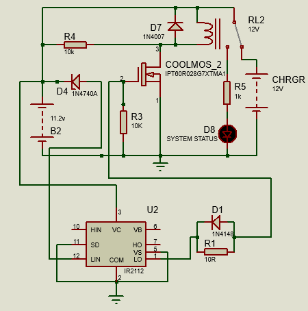
1. Battery Overcharge Protection CircuitPlease refer schematics. This circuit is based on zener diode. A zener diode when connected in reverse bias configuration and its cathode voltage below its breakdown voltage, the zener acts like an open circuit. When a voltage above zener breakdown is applied at its cathode terminal, the zener starts conducting from cathode to anode in reverse bias condition. Since the zener diode can also work in reverse bias, this feature of zener diode is useful for detecting the cut in voltage level of the battery.
When the battery voltage is below 12 V then the cathode of the zener diode (D4) will be below its threshold voltage value. In this case, zener diode will remain in non-conduction state and will not conduct current from cathode to anode terminal. As the gate of CoolMOS Mosfet is connected to the anode of zener via the mosfet driver, it will not get the required voltage to change it's state and it will act like an open circuit. Practically it is observed that although zener below threshold voltage will not conduct, still it has some current (in micro-amperes) which flow from its cathode to anode. This current is the leakage current of the zener.
The CoolMOS MOSFET is connected to the Low side of the driver IR2112 driver which is connected between the zener diode and the mosfet. As the voltage at the mosfet gate start increasing, it acts like a variable resistance and the value of this resistance start decreasing as voltage increases. Considering the mosfet, if the voltage across the gate and source is above 10 Volts, then the mosfet will be completely switched ON and will act as a short circuit, activating the relay. Therefore, the charger which is at NC (normally closed) path will get disconnected from the battery. The LED at the NO (normally open) path of the relay lights up to indicate the over charging of the battery. The relay is used for extra protection. A fuse of suitable rating can also interfaced into the common power rail so as to eliminate any effects of short circuit, thereby preventing collateral damage to the systems.
2. Battery Health Monitoring CircuitPlease refer the schematics. A complex system such as an electric car would be using a series of batteries to build up the necessary current and voltage requirement for the operation. So normally the charging circuit that we would require is a balanced charging system as it would result in a healthier and efficient battery. But for the sake of simplicity of design, we assume that the entire battery unit to be a single cell which provides the necessary current and voltage to all the systems. A good battery protection circuit monitors and prevents the excessive charging of the battery unit by constantly monitoring the current and voltage measurements. CoolMOS Super-junction MOSFET protects the circuit by breaking the power from source in the unlikely event that may lead to battery fire.
In the scope of this project, the battery health is monitored by two means:
- By monitoring the amount of expansion of battery due to the prolonged use, misuse, damage or overcharging.
- By monitoring the temperature of the battery as it might get heated up due to hardware or software glitch, heavy loads or simply factors such as rough conditions like excessive vibration.
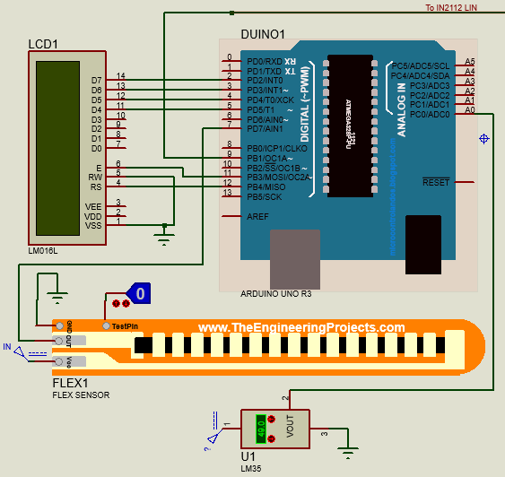
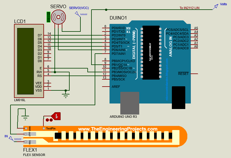
The expansion of the battery can be monitored by a flex sensor or a load cell. A flex sensor is nothing but a variable resistance unit whose resistance at a given point of time depends on the amount of deformation or bending of the element. This can be attached firmly to the surface of the battery. The changes in the resistance is constantly monitored by an Arduino Uno module. More technical details on the working of the flex sensor and it's interfacing with an arduino is explained in detail here. The load cell will monitor the compression load that is enforced on it. The interfacing of load cell depends on the type used. If the output is too low, a load cell amplifier such as HX711 can be used. More details here.
Battery temperature could be measured by any standard temperature measurement IC's such as LM35. LM35 is normally used to measure temperature of its surrounding. It’s output signal is proportional to the detected temperature. But at times, it can be sensitive or inaccurate and its output is not effected under any conditions. More technical details on the working of the temperature sensor and it's interfacing with an arduino is explained in detail here.
The arduino constantly monitors the output of both flex sensor/ load cell and temperature sensors. Please note that if you are using a load cell, it should be place between the battery expansion surface and atopsupport surface to allow considerablemeasurement of compression. Once a considerable change in flex/compression or temperature is found, it triggers a logic state output at one of it's digital pins. This digital pin allows the MOSFET to change its state to ON state which triggers the Automatic Cutoff Circuit and deactivates the power to the vehicle drive train, forcing the vehicle to a smooth stop while engaging the suppression system for avoiding a possible battery outburst.
Arduino Pin Interface data:
Flex sensor output------------> D7
Temperature sensor output-----> A0
LCD RS------------------------> D12
LCD E-------------------------> D11
LCD D4------------------------> D5
LCD D5------------------------> D4
LCD D6------------------------> D3
LCD D7------------------------> D2
Suppressionstatusoutput------> D9
An output element such as speaker can also be interfaced with this circuit to provide audio warnings.
3. Suppression SystemPlease refer the schematics. This is the main component of this system which does the work of suppressing a possible battery fire burst even before it happens. It consists of a pressurised suppressant canister and a high torque servo mechanism to activate the canister on demand. The whole assembly can be enclosed in custom made container in future for added safety. The container can be made with fire resistant materials such as Ceramics or another material which includes a fire resistant coating for protection. The whole assembly can be reused by just refilling or replacing the canister.
When the system is activated, the fire suppressant is released from canister by the servo mechanism causing the suppressant to fill in the battery compartment, thereby suppressing the fire.
Nitrogen is one of the gases that is used to pressurise the extinguisher. Nitrogen can displace the oxygen and thereby inhibit fire growth, eventually extinguishing the fire. It will generally have a powder or mix of powders depending on what class the extinguisher is. The canister can be replaced by a full fledged fire extinguisher system for heavy duty applications.
-----------------------------------------------------------------------------------------------------------------
Code Explanation1. Initialisation of sensors, actuators and displays
const int flexPin = 7;
const int TempPin = A0;
const int trigger = 9;
LiquidCrystal lcd(12, 11, 5, 4, 3, 2);
int servoPin = 6;
2. Initialisation of Arduino Pins and Serial mode
Serial.begin(9600);
lcd.begin(16, 2);
servo.attach(servoPin);
pinMode(flexPin, INPUT);
pinMode(TempPin, INPUT);
pinMode(trigger, OUTPUT);
digitalWrite(trigger,LOW);
3. Reading values from sensors
flexValue = digitalRead(flexPin);
TempValue = analogRead(TempPin);
float TempCel = ( TempValue / 1024.0) * 500;
4. Processing values and displaying them
lcd.setCursor(0, 1);
lcd.print("Temp Normal     ");
digitalWrite(trigger,LOW);
5. Triggering the suppression system in case of an anomaly
lcd.setCursor(0, 1);
lcd.print("Temp detected");
digitalWrite(trigger,HIGH);
servo.write(170);
delay(5)
-----------------------------------------------------------------------------------------------------------------
Planned Future Modifications:- Develop a general enclosure circuit that allows this existing suppression system to be integrated with any kind of EV system.
- Develop an additional sub-system that integrates a GPS to send emergency messages to predefined contacts such as workshop in case of an emergency such as a battery fire detection.
-----------------------------------------------------------------------------------------------------------------
References1. MOSFET data - https://www.infineon.com/cms/en/product/power/mosfet/500v-900v-coolmos-n-channel-power-mosfet/coolmos-c7/600v-and-650v-coolmos-c7/
2. MOSFET driver data - https://www.infineon.com/cms/en/product/power/gate-driver-ics/ir2112/
4. Proteus Packages - www.theengineeringprojects.com
****Since you read this far, we hope this project has caught your attention. No project venture is successful without the valuable feedback which we welcome from you****
-----------------------------------------------------------------------------------------------------------------


_ztBMuBhMHo.jpg?auto=compress%2Cformat&w=48&h=48&fit=fill&bg=ffffff)


Comments
Please log in or sign up to comment.