After seeing the large number of views my recent project (Servo Motor Art) got, I decided I probably should share some of my other Arduino based projects. The one I am presenting here is a flat panel LED display that is quite easy to build (although not particularly inexpensive). The main challenges in this project is developing the software, but I am providing a whole bunch of it that I have been developing over the past few years.
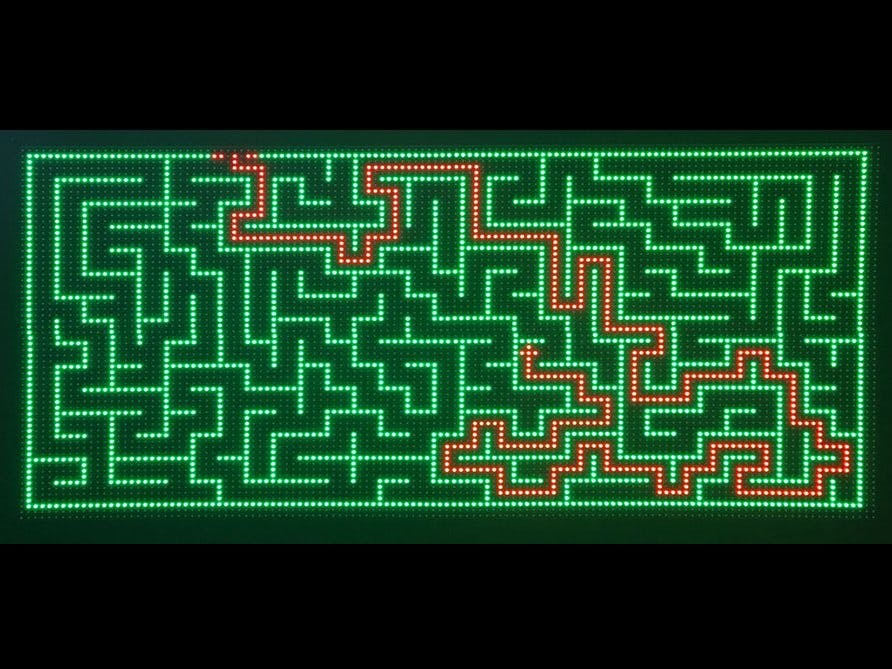
The nice thing about this project is that you can do so many things with it once it's built. The opening photo is of the panel displaying a maze and the solution it has found to escape the maze. This is just one of several programs I am presenting here. Here is a video showing the maze generator/solver in action (sorry about the video artifacts):
Here is another video of a Christmas show. I put it out in my front yard at Christmas to entertain the kids in the neighborhood. I know it over-exposed - too much contrast etc., but you can get the idea:
I am including here the software for both the maze solver and the Christmas show, as well as a Halloween show and a couple of other applications. They are all contained in a Zip file you can download.
This is actually my third LED display. To see the history and learn a little more about how these things work, I am including a link. It's supplementary reading but does give you some interesting information about how these panels work and how you go about programming them: Background on LED Displays
I am also providing another link. This one is the data sheet for the purchased panels. My display is actually made up of 4 panels, but this will give you some in-depth information about the operation of these panels: LDP-6432 Data Sheet (Our panels are actually model P7.62v2, not LDP-6432, but the data sheet above is good, as the differences are physical size only.)
Physical ConstructionI have 4 panels, each of which has 64 LEDs across and 32 LEDs vertically. I mounted them two across and two down to get a display 128 LEDs across and 64 LEDs high. They are mounted on a piece of foam insulation 2 ft. by 4 ft. I started out using a heavy plywood frame, but the final result was pretty heavy and difficult to move around. So I switched to a 2 foot by 4 foot piece of foam insulation. The foam was painted black with latex flat black. It must be latex, as regular spray paint dissolves the foam! (I found out the hard way!) The panels all have screw mounts on the back which you can screw standoffs into. I used male/female standoffs, so that two could be screwed together. Then I pushed them into the foam, until the outer standoff was completely inside the foam. When all were in the correct position, I pulled them out, put some Elmer's Glue in each hole, and then replaced the panel. This approach holds the panels firmly and permanently in place. However, don't use the glue until you have made the electrical connections, especially the 5 volt power. The power connections in particular would be hard to get to after the panels are glued in place. Take care when inserting the standoffs into the foam that you keep the panels tightly together. They form a continuous big panel if pushed tightly together, but leaving a gap between panels will produce a very undesirable appearance.
I put L-brackets on the bottom attached to 1 x 2 inch wood to form a stand. I also attached a handle to the top. Since attaching anything to this foam is somewhat problematic, I used over-sized screws and secured them in the foam with Elmer's glue. This approach worked surprising well. I can carry the whole thing around by the single handle on top, and I have never had anything pull out of the rather fragile foam.
Electronic HardwareAs I have already said, the hardware is pretty straight forward. The four panels are each dual-LED, tri-color 64 pixel by 32 pixel LED displays. Each pixel consists of a red and green LED. There are 2048 pixels and 4096 individually addressable LED elements in each of the four panels. Each panel includes shift register circuitry such that all 4096 LEDs can be controlled with only 12 I/O lines. Pixels can show as black (that is, completely unlit), red, green or yellow (red+green).
I mounted the panels two across and two down to get a display 128 LEDs across and 64 LEDs high.
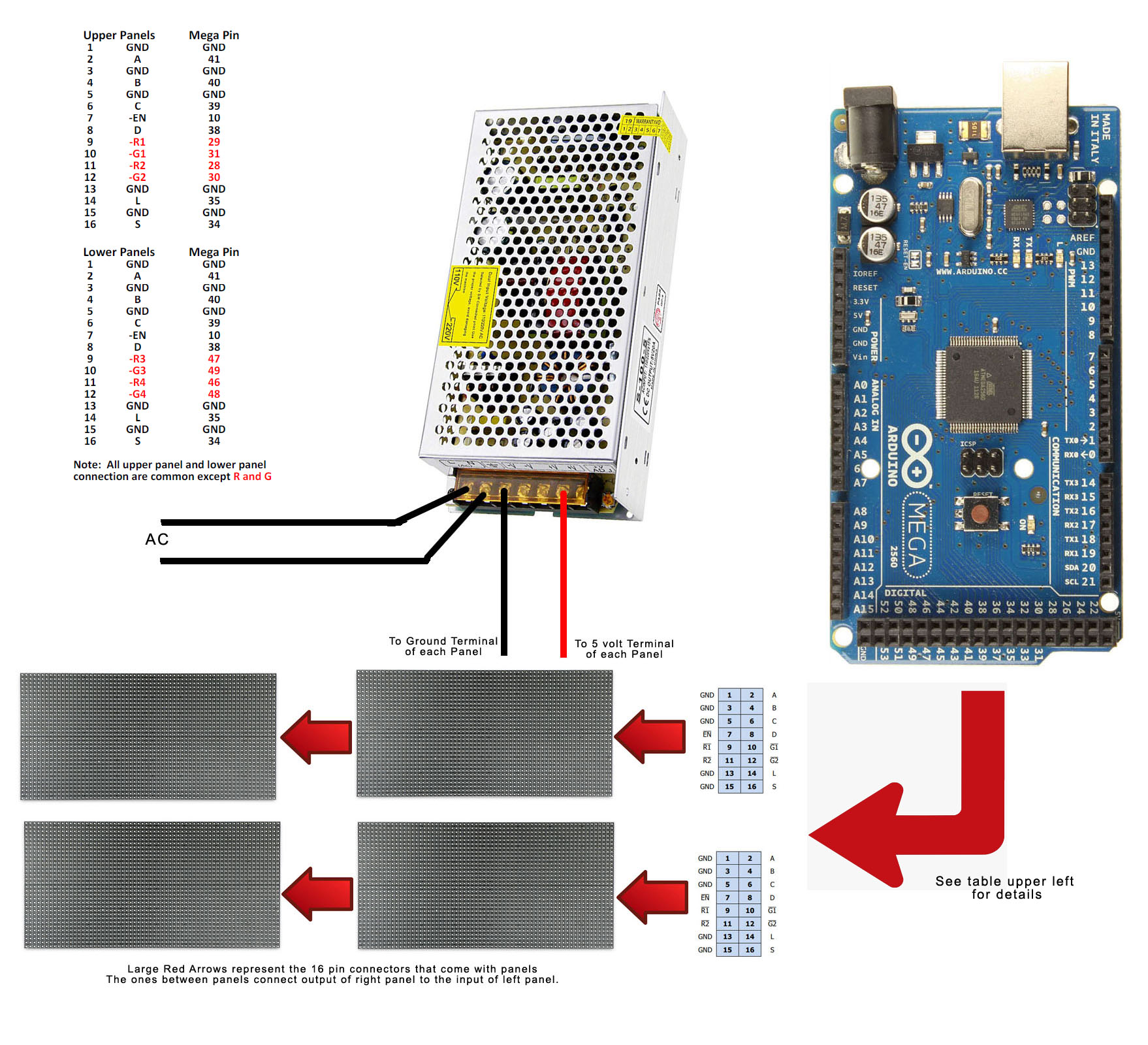
The photo above shows the rest of the hardware. The Arduino Mega is mounted on standoffs, but other than that, everything is just hot glued to the foam. (Use a 2 temp glue gun on low temp. High temp melts the foam!) A maze of wires comes out of the Mega and then splits, with half going to the top two panels, and half to the bottom panels. Each panel comes with a 16 pin ribbon cable. One is used to daisy chain the top two panels together. Another is used to daisy-chain the bottom two. The other two are connected to the input of the left-side panels and then go through holes in the foam to the back side, where we use breadboard jumper wires to reach the Mega.
Notice the red and black wires coming from the power supply. They go through other holes to reach the 5 volt power terminals in the center of each panel. Though it looks a little strange, I use a USB charger to power the Mega. (It is not plugged into the charger in the photo.) That makes it easy for me to unplug it and attach a USB extension cable when I want to connect to my computer for programming.
SoftwareGosh, where do I begin? I have a massive amount of software for this panel. Obviously, some of it is very unique to a particular application, like all the software that generates and solves mazes. But the tricky stuff is the underlining routines that powers the display itself, and this stuff is repeated in every specific application. The two most interesting things here are the subroutine that refreshes the display, and the one that displays both static and scrolling text.
Let's start with the refresh subroutine. This would normally be called by a timed interrupt, but for reasons I will get to in a second, we are pushing the Mega to its limits here, and the timed interrupt doesn't work. The Mega is being using here because it has lots of I/O ports, but mainly because it has 8K bytes of RAM. Although I can store the status of each two-color LED is two bits, it's faster to use a whole byte. But with 8192 two-color LEDs, we are forced to store multiple LED status in a byte. (Otherwise, we would use 100% of our RAM on this one table!)
Trying to refresh 16384 single color LEDs is bad enough, but when the refresh process has to unpack the data for multiple LEDs stored in a single byte, it takes too long. Even with direct port access and a lot of tweaking, the full refresh cycle takes about 19 milliseconds. So we are refreshing on demand, not by a timed interrupt. The Mega does the job, but just barely!
The second interesting topic is displaying text and scrolling it. I use an 8 x 8 bit font which is stored in a table which resides in program memory. My subroutines for static and scrollling text take a string input like "Hello" and turn it into a stream of data from the font table that can be displayed on the panel. Getting it to scroll is an additional complication, but the subroutine handles all that. You just tell it the string your want to scroll, where you want it to scroll, and what color you it to be.
I have included a lot of different programs or Arduino sketches in a single ZIP file. They are all multi-file sketches which display in the Arduino IDE as a bunch of different tabs. Each one contains some code specific to that particular application, along with the code for the display itself, such as the text font and the refresh routine. More details on the software are explained in the READ_ME file in the ZIP.


_wzec989qrF.jpg?auto=compress%2Cformat&w=48&h=48&fit=fill&bg=ffffff)


Comments
Please log in or sign up to comment.