


Hardware components | ||||||
 |
| × | 1 | |||
| × | 1 | ||||
| × | 1 | ||||
| × | 1 | ||||
| × | 1 | ||||
| × | 1 | ||||
| × | 1 | ||||
| × | 1 | ||||
| × | 1 | ||||
| × | 1 | ||||
| × | 1 | ||||
| × | 2 | ||||
| × | 10 | ||||
| × | 1 | ||||
 |
| × | 1 | |||
 |
| × | 1 | |||
Software apps and online services | ||||||
 |
| |||||
Hand tools and fabrication machines | ||||||
 |
| |||||
| ||||||
"Project Thor" Started back in 2006 before the internet of things was BIG. It's goal was to produce what is now termed and IoT irrigation controller which was to run on a farm wide WiFi network. The project was very active over a 2 year period and culminated with half a dozen controllers being built and installed. The whole point of the exercise was to gain a technological advantage for arguably the most advanced citrus growing operation in Australia located at Jamesville Station on the lower darling river.
For those with a keen eye the system was built around generic.NET controllers the idea to be as inter-operable with industrial equipment as possible. To that end the system used RS-485 on it's moisture probes and will communicate with remote I/O via modulus if needed. The software also runs on PC as it is not tied to a platform other than it's.NET and MS-SQL server back end which can be provided by any suitable computer or PLC platform. Without boring you with details we covered a great deal of territory in a very short time and now have hundreds of thousands of run time hours on the systems.
So it all works great and combines almost everything - why the change?
Well the original computers are not getting younger and they still cost lots. What if we could do all this in a $6 computer that ran on the smell of an oily rag, would this not be great ? Well for me this one video changed my mindset, if you could transmit a TV signal with this CPU then you could do a simple job such as irrigation control. There was also a nagging that Thor started at mid sized irrigation and I wanted better scaling extensibility. I really wanted the 1 or 2 valve up to the 100s of valves but I wanted to retain the distributed concepts in Thor that had worked so well. Besides if I was careful I could make them compatible that way I could have my cake and eat it !
Where to startSo I decided to start with two key areas, Irrigation scheduling and fertigation. The first important concept in the system is Logical valves, these are able to be configured to an electrical output in various modes and options. What makes this so good? Consider that a coil burns out and fries the output, your irrigation program needs no changes you simply re-route the electrical signal to a new output after replacing the coil and your good to go. If your more organised you plumb and wire spares on the manifold.
The second most important thing was the proportional fertilization system, without this you can't really farm. This consists of a PWM system with the pulse width being in seconds, this width is governed by the flow rate which is recorded against each valve. The section/valve flow rates are generally easy to measure or calculate and in case of drippers most are pressure compensated so the flow is accurate across a fairly wide operating range. The fertigation records volume pumped and there is a empty tank shutoff. All sounds good but the the point where the rubber meets the road is how Thor records what chemicals go where and in what quantity.
My main problem with the esp8266 in this project is getting my head around not having the power of SQL Server on-tap. However this is not so bad as I was no longer in uncharted territory but on well trodden ground with regard to what the data structures needed to look like and the relationships between them. So starting with the SQL table definitions from Thor I worked back to two structures for each, one of memory and one of eeprom. The web interface then sort of fell out in the wash as it had to support changing items in the data structure.
The first scheduling program while having some of the charms of Thor is lacking due to a finite number of programs. In Thor there are NO practical limits in the scheduling system and I felt a bit ashamed of putting any in this area but I needed the system to work and time was short. This also has the effect of focusing the user back on a per valve rather than per program shift which in my view is "wrong thinking".
There is now a shift based programming system, this is not quite as flexible as the original implementation but it will do for a $6 computer.
The programming methods both save to separate areas of the eeprom so the controller can be swapped between methods and not loose any program data.
This next screen was a staple of the old system, it show how I/O is mapped to the real world. Very easy to diagnose double ups or missing coils from this page.
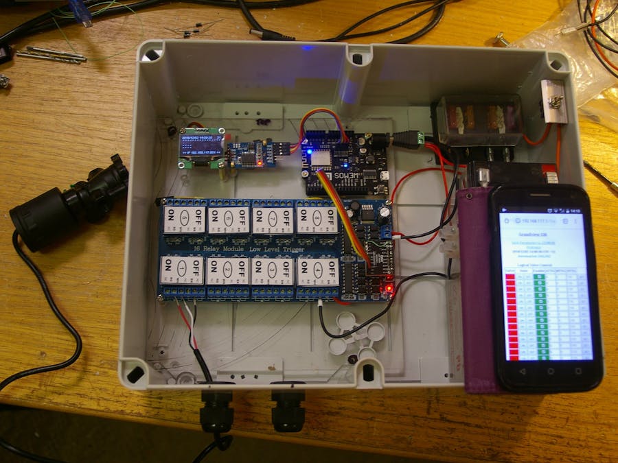
I wanted this unit to be able to be produced with off the shelf parts but the first problem as finding a cheap I2C relay board. I eventually settled for a garden variety board that sells for under $15 and fitting it with a I2C expander board ($2). This required minimal micro surgery, just one extra pin. I constructed a drill guide jig out of vero-board for this operation. The tricky part to this is that the expander VCC is 3.3 V and does not connect to the 5V VCC of the relay board, they only share a ground. The code is written for 2 types of expander and to allow translation/mapping from "native" to a bit/relay order that made remote sense in the real world. There is also mapping for local I/O.
I must have build a few to many prototypes as I wrote this page to help automate the checkout of the controller outputs.
This is how the UI for fertigation control worked out. There is a master and day enable as well as delivery method. The Tank is picked up by associating it via valve setup page. This allows different tank combinations to be used with each valve if necessary.
The main UI for valve control looks like this. TTG is "time to go", automatic (programmed) manual and default. The manual time only counts down when automatic is not on, that way you can add make up water to a daily schedule as need without altering the base rates.
It was decided to put an OLED display on the unit as a "confidence meter" as much as anything. It shows the date, time and IP address as well as valve and fertigation output status. This is more critical for double acting valves as they are normally not powered and only pulsed to change state. So an indicator you can quickly match against the valve status in the paddock is a handy field item. The RTC was my usual off the shelf DS3231 board which I found was happy to run at 3.3 Volts and also has addition eeprom storage. I found people actually looked at the temperature of the RTC (in the node setup page) to get the shading of the enclosure right. Handy side effect I had not really given much thought to.
The brick implementationThe board in this one was actually a truly bricked CPU as the I2C had gone to god during an infield diagnostic mishap. A reminder to always have all your wits about you not just half of them.
There are several other construction variations envisaged such as using a relay and battery shield to produce a controller in a brick/block format. This would be the second solar powered variant. This was the model to be used by me third trial volunteer. They didn't want to bring the valves back to a central point but wanted to do a wireless hop back via the AP. My range tests suggested 50 to 100 meters depending on if it was line of sight.
This version is promising but an internal/integrated battery or super capacitor as a power source would seem to be the go. Doing more with less power seems to be what makes it all happen. Less power, small solar panel, cheaper final assembly.
Real world testingI'm lucky enough to have friendly farming neighbors who also have backgrounds in software development. They have been on the bleeding edge despite their farm being a much bigger concern than my "prickle patch". These photos are from one of three of his irrigation points. The main water supply pipes are typically 200 or 250 mm
Of course I'm always lagging behind but it has happened. The "prickle patch" was swapped over in September 2019. We are are expecting an improvement in the prickle yield despite the Australian drought ;)
The point of this exercise is not only to act but to record. To that end a web service is being designed and tested to record, log and report water and fertilizer use. This was originally integrated into the control system but it seems logical to store this more centrally to give a better aggregated picture of the farming operation. Some aspects of this are for later parts to the story.
Special ThanksTo all those on the alpha and beta test team for putting up with faults and for putting your faith and crops in the care of my thoughts and imagination.
Update July 2022Well actually there have been a few but I'm too lazy to document them all. Newest version is always available on github as I do update it regularly.
Added
Email for reporting (send emails when fertigation tanks are near empty)
ADC input and alarming via email also works with master valve status.
Valves that are ALWAYS ON so their programs run when the rest are suspended.
Auto reboot on time and on time of day/week (with reporting)
Valve logging to the eeprom on the RTC. (Retains irrigation data even if CPU board is changed out.)
Backup and restore of programs also works now even between software versions.
Output Polarity for coil driving is now active as is the pulse width settings.
Arrgh.... OK that's it .... I'm finally done/over sticking manky relay contacts. Changed out the relay board out for 4 x L298 PWM modules coupled to the same I2C port expander chip. Swapped pilot valves to a brand that are repairable and added poly fuses in circuit with each valve. Just in time for the next irrigation season.
The new valves actually contain a small electric motor not a solenoid. You can still see the an old relay board behind the new drive board. This still does the coms switching and fertilizer motor contactor.
I have also built up another H-Bridge option with a different chip ready to test after this one. Then I might think about a custom PCB after I see "which way the cards fall".
Have added more to the I2C bus scan so it can be automated and email an alarm if things change. This was implemented to help diagnose intermittent inter board connections. There is also a shutoff option for fertigation if one of these should occur. So the procedure is you manually scan the I2C bus then save the configuration and the controler will use this as a reference for automated scans.


Comments
Please log in or sign up to comment.