


The project started a few months ago with the idea of building a self flying drone.We first thought of a quad-copter, but as it was already done by many people on the internet, we choose to create a flying wing.Right now, the project is still under development, but we hope to make it fly as soon as possible.
Just a quick reminder on some acronym :
- UAV = Unmanned aerial vehicles
- MCU = Microcontroller unit (A small processor with many peripheral like communication interfaces or timers.)
- LDO = Low Dropout (it define a type of power supply Integrated circuit that drop voltage from a voltage to a lower one)
- PWM = Pulse width modulation ( define a type of modulation)
In order to make it fly, we first needed a way to create and test the hardware/software.In order to avoid more complex problems due to aerodynamics, we first use a 3D printed plane from a company called Eclipson.As the first flight will probably be a failure, we needed an affordable plane capable of being repaired quickly.We selected the EBW-160, UAV version. The UAV version is the same as the EBW-160 but with "holes" for all sensors. And yes, the 160 in the name mean 1.6m.We started by 3D printing all needed part (And it was quit long) ! We then followed all instruction given by the manufacturer and it turn out great.
We started by 3D printing all needed part (And it was quit long) ! We then followed all instruction given by the manufacturer and it turn out great.
Then, we started designing a board that should be able to fly autonomously using multiple sensors.
Then, we started designing a board that should be able to run autonomously using multiple sensors.
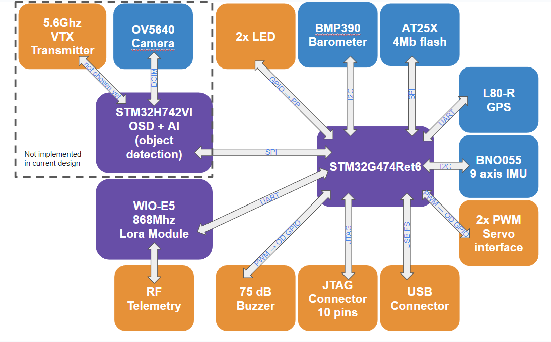
The board V1.0 used an STM32G474Ret6 as main MCU. This is basically the brain of the drone (also the memory).It will run the code, store data, calculated trajectory, and move the flaps/motor speed.Then we added a power supply made for 3A, that used a lm1117 LDO and a buck converter with some filter (refer to schematic for more information's).We also added a 4mB of flash that is used to store the flight path.Well now the only thing missing is some sensors!We choose a basic GPS module with a UART interface from Bangood, a MPU6050 that use the i2C interface, and the BMP390 that also use the I2C interface.
The Mpu6050, or also called IMU (Inertial measurement unit) is a MEMS capable of sensing acceleration on 3 dimensions.The Bmp390 is also a MEMS use to sense the ambient pressure.This pressure will then be send to the MCU in order to make calculation and find altitude.
The V1.0 was great, and let us time to discover how to use all sensors, and start developing the software. But many problem occurred.
- First, the IMU (Inertial measurement unit), here the MPU6050 was not powerful enough.The resolution of his sensor wasn't good enough for what we were doing, and complex algorithm should be implemented into the main CPU(quaternion or Euler angler calculation.. etc.).This means that the MCU will have to run faster in order to be able to run the program correctly.
- Second, we used a level shifter.This level shifter had to convert a PWM 3.3V coming from the CPU to a PWM 5.V, used for motor control.The new idea was to put the GPIO that generates the PWM into an Open Drain mode.This mode lets the GND connected, but the high level connected to a floating pin.So, by using a 5V pull up resistor,the main engine controler or ESC will have a 5V high level and a 0V low level.
- Third, the 3A power supply is totally overkill! As the ESC already embedded a BEC or buck converter, we can use it to pull downVoltage for maximum 12V to a 5V. And as the ESC is now getting his current directly from the battery, we only need a few mA.
We then tried to do do some test on the board V1.0 and this is how it turn out !
This time, we have been trying to avoid as many errors as possible, and we also complexified a lot the board (Yeah I know this sound crazy)
Thanks to Seed Studio and Seed Studio PCB manufacturing for the sponsorship. With them, I hope to build the perfect flying wing using only open source.
For more information's on their PCB assembly services, please check : https://www.seeedstudio.com/fusion.html
We started by switching the old 3A power supply by the BEC of the ESC. Now, when we power the board,the battery voltage will be reduced by the BEC from approximately 12V (for 3S lipo) to a 5V.As all components (except the two servos) need a 3.3V VCC, we also added a 800mA 5to3.3V LDO.
We also added a way to monitor the battery voltage by using a simple resistor bridge.This bridge takes the 12V from the battery and divide it by 4.Now we have a 3V that can go into the ADC of the MCU. Using this ADC, we can now monitor the voltage.
Now, it could be interesting to know how much power the board is using. By doing so,we could predict how many time the remaining battery will keep running.You can find some example here.As the battery capacity is given in XmaH then it mean we can run a full hour if we only consume this X MA.For example, if we have a 900mAh battery, and a system that uses 450mA. Then we will be able to run it for 2 hours straight.So we have to measure the consumption of our system in real time. To do so, we added a 0.002 ohm resistor like this.
We then measured the voltage drop in this resistor and applied U=R*I or I= U/R.
You may wonder, why we used a 0.002 ohm resistor ?The answer is simple ! The power dissipated in a resistor is equal to P = R*I*I. So if we chose a lower resistor,it could then be able to let more current flow before it burns. We choose a 2W resistor, so by doing some quick math it should be able to flow approximately 32AWhen creating this board, the idea was to measure current flow twice. By doing so, we will be able to know exactly the currentConsumption of the motor and the board itself. As the current measurement resistor for the board is placed in series with theLDO (max 800mA), the resistor can then be smaller and have a maximum rating lower.
Like the first prototype, we needed a way to measure the acceleration on 3D axis. To do so, we choose the Bno055 IMU.This IMU is really impressive, because it can measure acceleration on 3Axis, Acceleration around this 3Axis (also called Pitch/Yaw/Roll) and the magnetic field of the earthIt also embed a small CPU use to process all this data, and return many information'sFor example, we can have the position in space relative to the calibration point or relative to the earth magnetic field. This is called Quaternion! We also have the Euler angle.This is needed to know which way the sensor is heading for example.
We could have implemented these two algorithms into our main CPU, but it will take some CPU calculation time.Thanks to Bosch, we don't need to do it, and just read this data out of the IMU.
Then for test purpose, we should have a way to know exactly the Altitude/Speed… and much more from the ground.To do so, we added a telemetry system using a Lora Wan protocol and the Wio-E5 Lora module. This protocol is only usable withLow data speed, and can't go higher than a few kB/s. But as it is used for telemetry prupose only there is no problem here.This module is quite simple to use, as it only needs a UART interface, and some AT command.But as I'm not good enough in radio frequency, I choose to let C26 and C39 not soldered and add a Ferrite bead footprint just in case we need to add some filter (LC or RC) at the output of the RFIO.These footprints can also be used to adapt antennat impedance to the module impedance (for example with PI bridge).For the moment, I'm probably not using this component at his maximum.We will then gather information from the UAV to a computer and print it using a python script to create graphs and more.
For those who are interested in all wiring and PCB documentations, please send me a message on github :D
Now, lets talk about software!
The basic idea was to split the trajectory calculation, the integration of the flight plan and the stability into 3 parts.We first started by creating libraries for all components, that is optimized for our need. We then added PID control in order to stabilize the aircraft.This PID controller was made by ARM and is part of Arm_math.h library.
Right now, we are currently trying to calibrate properly the PID constant to ensure the system is able to react with enough speed, but not too much to avoid oscillation.We are planning to the test the first part of the software within a month and we will share the test result here! (Obviously it took a lot longer to make it work, and it's still not working properly)
Small update done 06/05/23
Today, the main theme is PID, or proportional integral derivative. For those who don't know what a PID is or how to use it, you could find some great example right here !
The best example of a basic PID use is when you are driving a car and put it into cruise mode at 100 km/h. If the wind starts blowing, then the car willstart to slow down at 80 km/h. To compensate for this, the cruise mode should accelerate in order to reduce the error between command (100 km/h needed) and actual speed (80 km/h).That's how the proportional gain works in PID. But by doing this, the autopilot will keep accelerating at max power until it reaches the needed speed. Then it will break (also at maximum power), until it reaches 100 km/h. As you can imagine, this can't be added to a car.
In order to work, the car should accelerate harder if the error is big and slower if the error is small. This is done by the integral gain! For now, I am currently trying to find the correct PID coefficient. This gain or coefficient should be high enough to make the system react quickly but not too high to avoid oscillation (systems that oscillate between over and under the system command). The proper way to do it is to make it flight with stock settings, and then measure how the aicraft is flying (using IMU data). Then simulate the PID again with actual flight data, in order to make settings better.
Now,how do we integrate those PIDs into our project? First, we need to understand how forces are applied to the flying wing when it wants to move. For more informations please take a look here !
If the plane nose starts pointing at the ground (the yaw axis moves clockwise), then the plane should move both flaps down to compensate. If the plane nose starts pointing at the sky (the yaw axis moves counterclockwise), then the plane should move both flaps up to compensate. By applying this method to all three axes and using three PIDs, the plane should be able to follow a command.
For now, there are two major problems:
- The first one is that the low-pass filter intergated in the IMU wasn't running. This is quite a big problem because of the high frequency.movement (ultra-quick movement variation) is measured, and the plane tries to compensate for it. To solve this problem, I used a basic FIR filter.but I could also choose a Kalman filter. For now, I don't understand how the Kalman filter works or why I should use it more, so I only usebasi low-pass filter. Please check !
- Second, the function to compensate for PID is not called often enough. This causes a big latency between actual flap movement and board movement.
Then, is also made the USB active by using STM32Cube IDE middleware. If you want to do the same please follow this tutorial. This USB will be used in the future to flash the flight plan on the external 4 MB flash. But for now, it is used as a debug port using a virtual COM port and docklight. Be aware that not every cable has a data cable in it. I was debugging for hours until I found out that mine was only a USB charger and wasn't made for data transfer.
Last but not least, i also created some drivers for the GPS. Actually those were not optimized for speed, but as GPS reeding will only occured once every second, execution time is not a big deal. The driver is only reading a certein number of char incomming from the GPS. This char are part of NMEA data. When testing, the best I could get was a GPS resolution of around 2m. But for our applications, this will do the job.As those tests were done inside, I could probably go down to a 1.5-meter resolution.
I will update soon the ReadMe on github to ensure everyone can flash the board and run the software correctly using CubeIde
Major update on 31/07/23
Hi, for the past few weeks, I have made a lot of changes in software development.It's possible that you're wondering how this is working. Although I am not an OS expert, I will make an attempt to explain as clearly as possible.I started by adding a small and open source exploitation system.I chose FreeRTOS because it was well-documented and straightforward to integrate with the ARM cortex core.It makes the system able to use multitasking with a mono core processor.
You may wonder how this is working ! Well 'I'm not an OS expert but I will try to explain as simple as possible.
The first thing to understand in an exploitation system is the concept of a task. Each system can be divided into multiple sub programs that will run independently.The most basic example is a weather station. In this case, you could create a task for :
- Reading temperature
- Reading humidity
- reading pressure
- Show data on a screen
Any task can be executed without any issues.Although the system is more complex in my case, I have broken it down into tasks like this:
- Read IMU --> Here the system will read all gyroscope sensor data. As the BNO055 I have didn't have the correct version, I can't make it to work with data ready interrupt.
- Read BMP --> Here the system read atmospheric pressure and calculated an altitude based on calibration data. (This should be explain in details later)
- Read GPS --> Here the system read gps incoming data and extract information's.
- Read Battery --> Here the system read the battery voltage and the current consumption. It will then estimated a remaining flight time.
- Send telemetry --> Here it will send all needed data using a LORA WIO-E5 module to a python script. We will then show it on screen.
- Control flaps --> Here the PID will be executed and the flaps will be move
- Control engine --> Same as control flaps but for main engine.
- Trajectory calculation --> Use CORDIC to calculate trajectory
Since we only have one core, the OS will use a scheduler to execute every task when necessary.For more information on the scheduler, please go here.
Each task have an associated priority, and let know to the scheduler the most prior task.
Heap size ?
It's important to note that the task can be completed or left unfinished. The scheduler can choose to switch to another task first and then come back to this one later.All the necessary data to restore the task will be stored in a memory location called the HEAP. To restore correctly, you must give the correct amount of heap to your task, otherwise the system will go into the HardFaultHandler.To determine the appropriate amount of heap, I attempted to start with the minimum size and increase it until the system no longer encounters HardFaultHandler.Although this method may not be the correct one, it worked for me.
Semaphore or mutex ?
In this section, we will learn about mutex or semaphore. As the task can leave at any moment, it can leave at critical moments (during a print or during sending SPI/I2C data).This will cause a bad reading or bad printing. To avoid it, you can choose to add Mutex or semaphore.I did have some problem with the i2C bus which was shared by the IMU and the pressure sensor. To avoid problem a mutex should be placed before every I2C use. For more information about mutex please go here.
How to add FreeRTOS on STM32 CUBE IDE ?
First open your . IOC and look for Middleware category. Then click on FreeRTOS
The first thing to do is choose the interface. In my case I choose CMSIS-V1 but both of them are a valid choice. As i understand the interface is only the library use by freertos.
Then find the Tasks and Queues menu and start by adding your task and the affiliated priority.
Then go into Config parameters and look for FPU/MCU. If you have a CORTEX M4 or higher, a floating point unit (FPU) should be available so you probably want to enable it.
Then you can change the total heap size to allocate more heap to each task.
And then go into Heap Usage to split this heap between task.
And here you go ! You have FreeRTOS running .
I also find a small mistake in the current version of PCB (REV 2.0).The UART between WIO-E5 and MCU is not wired correctly and make it impossible to send data using LORA.This will be patched in the next version but for now, I decided to cut both wires (RX and TX) and re solder with some small wire in the correct place.
I'm working on a Python script that visualizes data coming from the target. This should simplify the process of debugging and analyzing data.
Update Frebruary 23 2024
It's been a while since I last updated, so I had to cover various topics. As you can expect, major update has been done on software development.
- Let me start by introducing the new software architecture.
Thanks to Freertos, the software is now much quicker and simpler to develop ( simpler because the code is now split into dedicated task, and quicker because some more important section of code can be executed more than less important one).
As you can see in the above diagram, the software is now composed of multiple tasks.
- 1 - PID tasks
The PID task is probably the most important task to run. It reads Euler angle (pitch, roll and yaw), and then run the PID algorithm in order to align each axis with a recommended value. Those values can be set in real time in the command structure. This will then lead to a trajectory change. With the help of the new system, PID control is now much quicker.
- 2 - Telemetry task
The telemetry process gathers all data from the vehicle and transmits it via a Lora module (WIOE5). Those data will then be recovered by a ground station and use for future improvement. In order to keep track of data type, a basic transmission protocol has been established.
For example, if the vehicle needs to send 0x12345678 and its data is a left flap position, the encoded payload send is now 0x10 12345678
- 3 - Battery monitoring task
This task is pretty basic. It measures battery voltage and current consumption in order to determine how much flight time is left.
- 4 - GPS monitoring task
The GPS monitoring task reads the position of the aircraft in three dimensions every second. As the GPS refresh rate is only 1Hz, no need to read data more than once every second.
- 5 - Pressure monitoring task
The pressure monitoring task reads pressure from a BMP390 sensor every second. This is used to measure the ground altitude in real time. In order to do so, the aircraft first need to know the pressure at ground. This is done by using a basic formula:
Sometimes, in long flight, pressure can increase or decrease in the area. This will lead to a change of calculated altitude (as the calibration pressure doesn't change). To compensate this issue, we thought of recalibrating the barometer in flight using GPS data. For example if the altitude send by the GPS is more than 10% different from the altitude measured by the barometer then the barometer is recalibrate.
- 6 - Main task
This task could be assimilated into the main in Arduino or C. But in our case this function will only start to be executed after a High G interrupt. This means that it will start after throwing the aircraft.
For now, this task is only used for test purpose.
- Second thing, I also add a bootlader. For those who don't know what is a bootloader, it's a small part of code execute every time the system boot or reboot. In our case, this part of the code is necessary to put a flight plan into the external flash memory. To do so, the system will wait 10second for a USB activity. If there is no USB activity, then the system will start as usual. But in the other case the system will start flashing external memory until a <END OF FLASH> string has been received.
As you can see, the data coming from USB is only strings. So, I also added a converting function to transform string to coordinate.
All the python part should be done as soon as possible.
Last but not least, I also tried to use the inertial measurement unit to get the current position of the drone.
If you had already done a few basic physic courses you should know that the position in space can be found by integrating the actual speed, and that the speed can also be found by integrating actual acceleration. That's great because our IMU have already given us acceleration.
In order to keep things easier, I will only speak about one axis, but as you can imagine this will be the exact same protocol for 3 dimensions. As we get acceleration from 3 axis, just copy/paste the code for every axis.
But now, how to do integration using real time software, without heavy calculation load? The awsner is quit simple! First you need to know that integrating data in time, is exactly like getting area under the data line.
For numerical data, this can be simplified as a square! For example if we read data from an accelerometer at time n-3 and then read another data at n-2, the area of the current square is ((n-2) - (n-3)) * (sample n-3). This can be found by using the area of the square formula = l*L = Area.
But, by doing so you will only get speed variation relative to the last speed measurement. You should then store the value found from the last computation and add the new one together.Again, be really careful because by doing so you will have to set the first speed at 0m/s. If the aircraft is moving when doing so, this will lead to speed error in flight.
The code should look like this :


Comments
Please log in or sign up to comment.