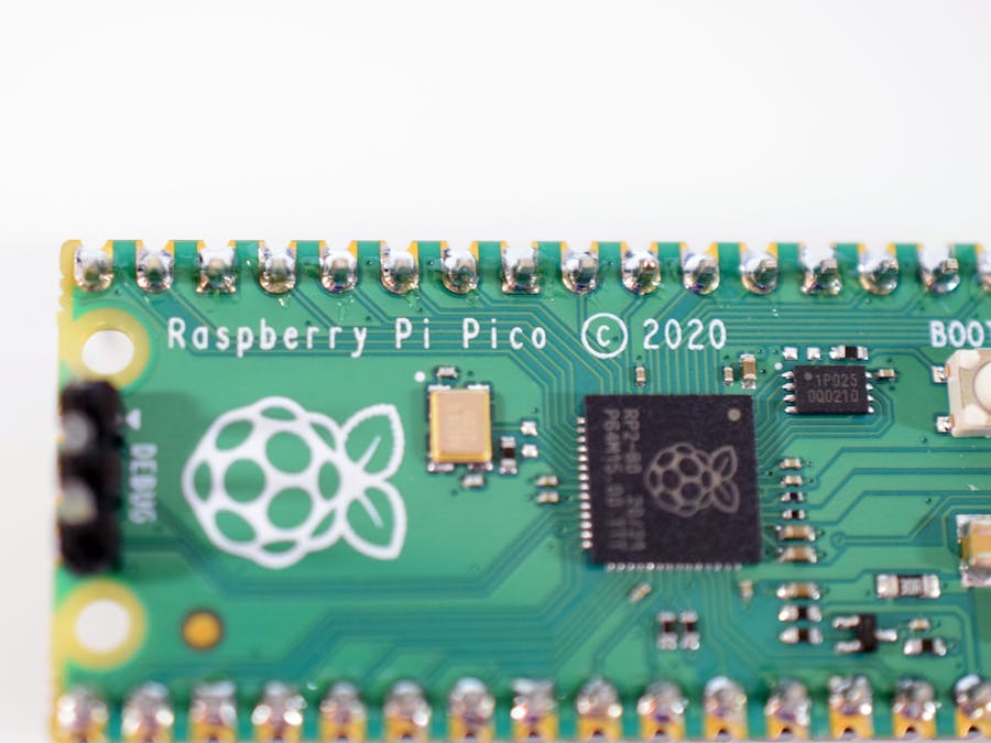
You're probably used to hearing about Raspberry Pi in regards to their lineup of small, credit card-sized computers that are able to run Linux operating systems. They're great for situations when low power, great connectivity, and plenty of compute capability is needed, but it falls flat in situations requiring real-time performance and precise timings.
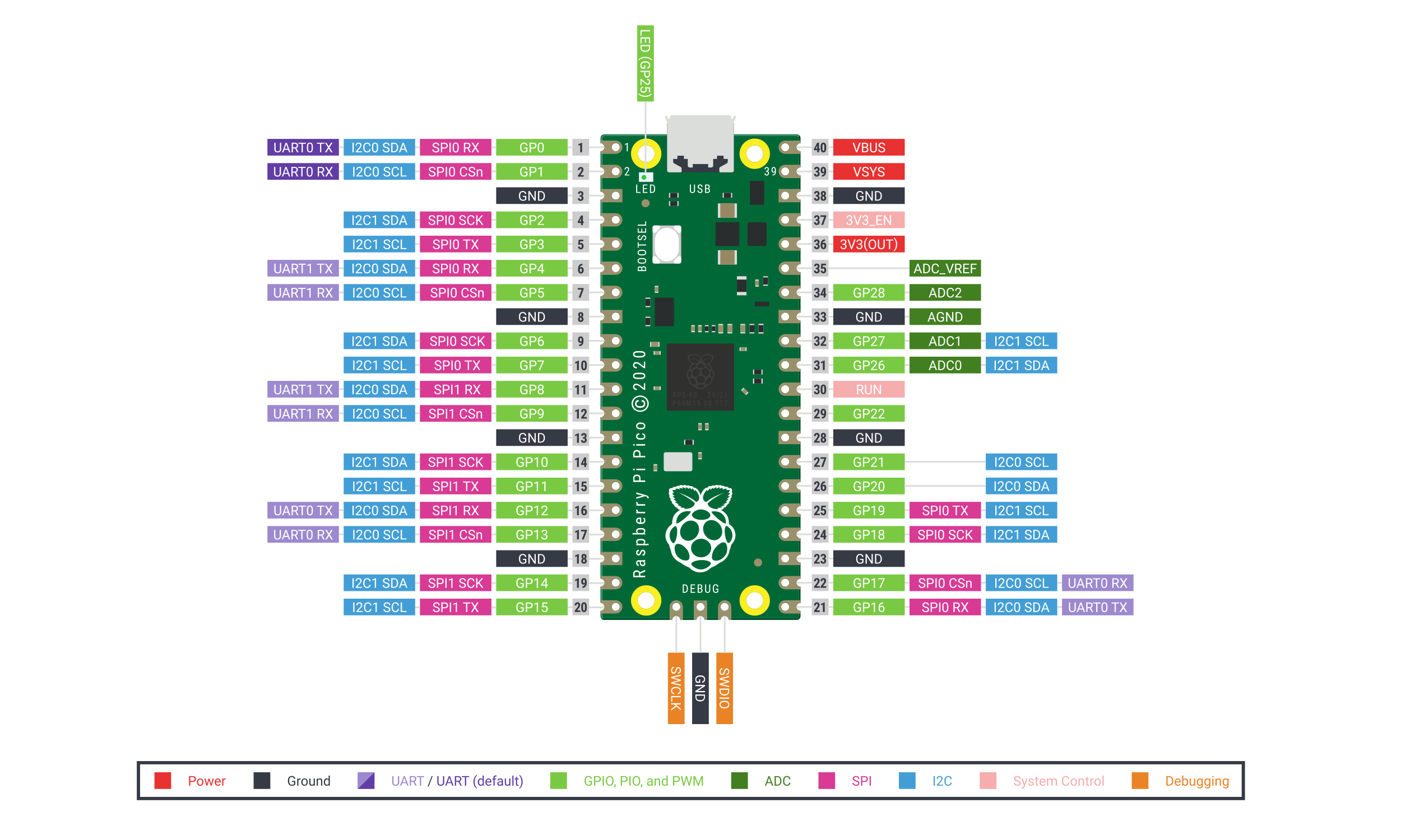
This is where the Raspberry Pi Pico excels. It has plenty of great peripherals, including I2C, SPI, USB, and more. The Pico contains two fast Arm Cortex-M0+ cores on a custom chip, along with a special subsystem called Programmable I/O, or PIO for short. It lets programmers create specialized state machines (up to 8) that can handle IO tasks with pins without the need for tons of CPU interaction, thus freeing up the two cores for other tasks.
SDK OverviewIt's fairly difficult to just load up a text editor and start programming for a board with even moderately advanced features. A software development kit (SDK) is simply a package of libraries, a compiler/linker, debugger, and sometimes a framework. So rather than toggling specific registers in assembly and trying to set up an assembler for compilation, the SDK can provide the tools necessary instead.
Installing the Toolchain and SDKThis guide covers the C/C++ SDK, not the MicroPython one, and assumes development is taking place within a Debian or Ubuntu-based OS environment.
Begin by creating a new directory within some kind of user folder, such as in the home directory with the following command:
mkdir picothen enter it by typing
cd picoNext, run the following three commands for installing the SDK and updating the USB library:
git clone -b master https://github.com/raspberrypi/pico-sdk.git
cd pico-sdk
git submodule update --init
then leave that folder and go into the pico folder with
cd ..and finally clone the examples into another folder called pico-examples:
git clone -b master https://github.com/raspberrypi/pico-examples.gitThen just run the next two commands to install both CMake and the GNU Embedded Toolchain for Arm, which is how the code you write will get converted into machine instructions:
sudo apt update
sudo apt install cmake gcc-arm-none-eabi build-essential
And that's it! With the toolchain and SDK now installed, it's time to begin programming the Pico.
Blinky LEDBlinking an LED when getting started with nearly any new microcontroller is one of the first things a developer will do, and the Pico is no exception. From the pico folder, type
cd pico-examplesto view the example projects. Then create and enter the build directory with
mkdir build
cd build
and create the PICO_SDK_PATH environment variable with
export PICO_SDK_PATH=../../pico-sdkand finally run cmake with
cmake ..By default, CMake is configured to generate Release builds, which don't have the information required for debugging. To build a debug version, run
cmake -DCMAKE_BUILD_TYPE=DebugNow we can get to building the blink program. Type
cd blinkto get to the blink example folder. Its contents should look like this:
There are two options here for building. The first is to simply run make or make -jT where T is the number of simultaneous processes (normally the number of cores your CPU has), so in the case of a Raspberry Pi 4, you would run
make -j4and now you should be able to see both the blink.elf and blink.uf2 files. The elf file is used by the debugger, whereas the uf2 file can be copied over onto the RP2040 mass storage device.
Programming the Pico is extremely simple. While holding down the BOOTSEL button on the board, plug in the micro USB cable.
You should now be able to see a device called something like RPI-RP2 with the following files:
On the desktop, drag the uf2 file from the previously used build/blink folder to the USB mass storage device. This will cause the explorer window to close and make the Pico start blinking its onboard LED. You can also plug in the Pico the same way (holding down the BOOTSEL button while plugging in the micro USB cable) and then search for the attached disk with
dmesg | tailand then creating a new directory for the filesystem:
sudo mkdir -p /mnt/picoand mounting the device:
sudo mount /dev/sdDp /mnt/picowhere D is the device (a, b, c, etc.) and p is the partition (should be 1). So for the Pico on sda, it would look like
sudo mount /dev/sda1 /mnt/picothen copy over the file with
sudo cp blink.uf2 /mnt/pico
sudo sync
and then unmount it with
sudo unmount /mnt/picoIf you have previous experience with C or C++, then you'll know that to copy data from one array to another, you normally need iterate from the source array (read it) and then move that same data into the target array (write it to the destination). When working with something like an Arduino Uno and a string of addressable RGB LEDs, the Atmega 328p has to take a buffer of color data and transfer it over a GPIO pin bit-by-bit, which means the CPU can't do much else.
You could also try imagining a system with two devices where one is sending data to the Pico over some protocol and the Pico then needs to put that data into some kind of buffer in RAM for later use. Rather than having a CPU core constantly wait for new data to arrive and then store, why not have dedicated hardware do that? This is the underlying principle for direct memory access (DMA).
Head back to the pico/pico-examples/build folder and then enter the dma folder with
cd ~/pico/pico-examples/build/dmaYou should see three folders related to various examples, and for now we'll look at the one called hello_dma. Within the folder, it should look like this:
If you run make here it will build the usual elf and uf2 files that you can load onto your board. You can view the output by attaching a UART to USB converter to the Pico's hardware UART pins and a ground pin. Now we'll take a look at how the code actually works. Head to the folder with the source code by entering
cd ~/pico/pico-examples/dma/hello_dma/and then viewing the hello_dma.c file within a text editor. It looks like this:
You can see that there's an array of characters (chars) called src that gets stored in flash memory when the program is loaded onto the chip (because it's const). Below it there's a pointer to a location in memory called dst that has the same amount of space allocated as the constant array. After calling stdio_init_all() which sets up the UART port for functions like printf, you can see that a DMA channel is requested called chan. Then from line 27 to line 30 a dma_channel_config structure is created and configured to increment the source and destination pointer with each transfer, along with being set to transfer 8 bits at a time.
Within the dma_channel_configure() call, the destination and source pointers are set, as well as the number of transfers. Once the call is made the transfers start immediately and complete after the correct number of bytes is transmitted. Since the processor has nothing else to do in this example, dma_channel_wait_for_finish_blocking() simply waits until the transfer is done and then returns. Finally, the data from the destination buffer is printed to the UART peripheral using puts().
The Raspberry Pi Pico has so much potential, and it will be exciting to see what people can create with this small, cheap device. For more information on the SDK, check out this link, or view the Pico's homepage to learn more.


Comments
Please log in or sign up to comment.