

Hardware components | ||||||
| × | 4 | ||||
 |
| × | 1 | |||
| × | 1 | ||||
| × | 1 | ||||
Software apps and online services | ||||||
| ||||||
| ||||||
 |
| |||||
Hand tools and fabrication machines | ||||||
 |
| |||||
| ||||||
Trying to hand-solder can be difficult, but what's even harder is hand-soldering tiny SMD components to a small PCB - like trying to pick up individual grains of rice with tweezers small. In this project I will show how I designed a custom PCB and soldered the components to it with only a soldering iron, tweezers, and a microscope, which was sponsored by banggood.com.
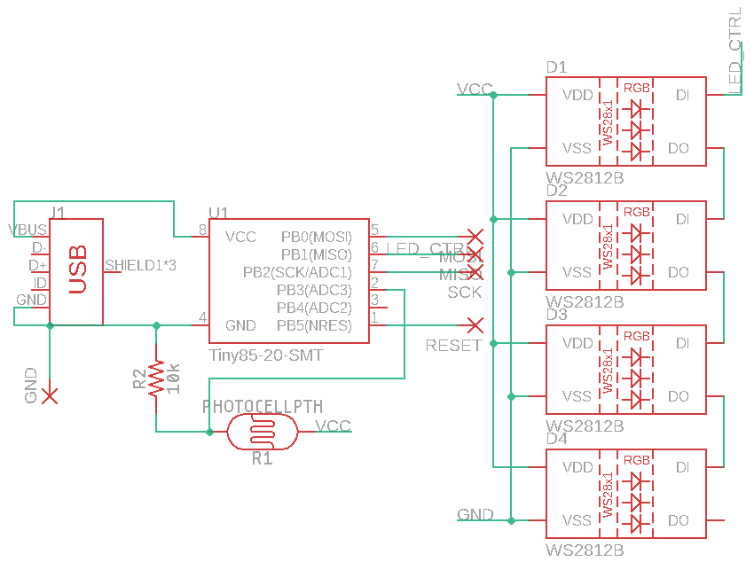
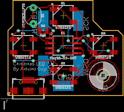
I started by firing up EagleCAD, a nice software package that lets users put together schematics and then boards with ease. Sparkfun has a set of hardware libraries that contain hundreds of components. I then laid out the schematic in the editor, attaching the LEDs to the ATtiny85, along with the micro-USB connector and variable light resistor. Then I generated a PCB from that schematic and laid it out into a very small footprint. Since Eagle was acquired by Autodesk, there is now an ability to push or pull PCB designed to and from Fusion360. I pushed my PCB layout into Fusion and designed a base around it, along with a top that had cutouts for the LEDs to shine through. A digital design of a PCB is fine, but how do I get it made? I sent the.brd file to a company called Oshpark, who fabricates PCBs. After about a 2-3 week wait my boards had arrived.
After charging the battery-powered microscope it was time to solder the components. When attaching SMD parts to a PCB, it's best to start small and work your way up to larger components. The smallest part on the board is the 0805 10k resistor.
First, I put a little glob of solder on one pad, then while holding the component with tweezers I took the iron and applied heat to one end. Then after it had cooled I soldered the other end onto the other pad. Next was the micro-USB connector. I started by soldering the largest parts of it onto the anchoring pads to prevent the traces from being ripped up. As seen on the image only the first and last pins are of relevance to the circuit.
So that's all I soldered to the pads. Then it was time to connect the star of the show: the ATtiny85. It's package is SOP-8, which means that it has 8 pins, 4 on each side. So I began by laying down a bit of solder at pin 8, then soldering pin 4, then pin 1, and finally pin 5, then I soldered all of the rest.
It's best to solder in a corner-to-corner pattern to prevent the package from moving when other pads are heated. Soldering the 5050 WS2812b LEDs happens in a similar way, with it being attached in a star-pattern.
Lastly, the through-hole components get soldered, and in this case it is the variable light resistor. Simply poke each lead through the holes and then solder them to the pads.
The code for the lights is pretty simple. First, it takes a reading from PB3, also known as Port B 3, and then it maps it to a value between 60-100. Then it sets the LED brightness to that level. The WS2812b LEDs are connected to PB1. So it then fades through blue to red and then back to blue. After 10 seconds the ADC gets read again, and the brightness is changed.
ProgrammingThe ATtiny85 doesn't have UART, so how does it get programmed? There are 3 pins on it that can program it: MISO, MOSI, and SCK. These are part of the SPI bus, allowing for ICSP. There are separate ICSP programmers, but they can be expensive. Thankfully, there's an option to turn an Arduino, such as a Nano or Uno, into an ISP programmer. Simply open the Arduino IDE -> File -> Examples -> Arduino as ISP -> Arduino as ISP, and upload that to the Arduino. Then solder on 5 wires to the pads on the back of the IC to the pads MISO, MOSI, SCK, RESET, and GND. MISO gets plugged into pin 12, SCK into pin 13 MOSI into pin 11, RESET into pin 10, and GND into GND.
Also make sure to add a 10uF capacitor between the GND and RESET pins on the Arduino. Now go back to the IDE and add the following link to the "Additional boards" section in Preferences:
Then install the boards from the board management section. After that has finished select "ATtiny85," internal 16MHz clock, and Arduino as ISP as the programmer. Then upload the attached code. But wait, it won't work. That's because the ATtiny's ship without a bootloader, so first select "burn bootloader" and then upload the program.
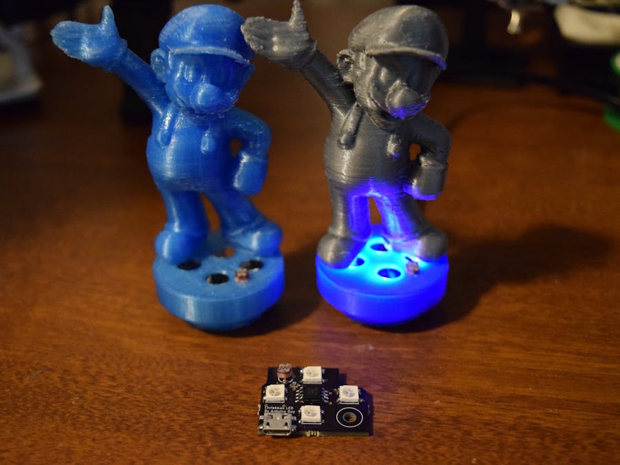
I printed out the base with PLA at about 205C and .3mm layer height. The figurines were printed in PLA as well at 205C and .1mm layer height.


_t9PF3orMPd.png?auto=compress%2Cformat&w=40&h=40&fit=fillmax&bg=fff&dpr=2)


Comments