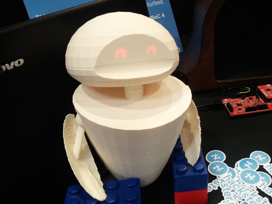
Eveii, pronouced "EE-vee": like Eve from Wall-E, version II :)
This little creature senses when you're nearby, or when you pick it up, and responds to that. I built it for Embedded World 2016, as a collaboration with Cypress Semiconductor. Right now, it only senses two different states, but I hope to expand it into a multi-talented robo-prodigy sensor hub!
The PSoC kits need to be programmed from a Windows machine, so go ahead and follow the directions to set up the PSoC Creator IDE. Get PSoC Programmer, too, so you can update the BLE dongle if need be.
Note: The website may ask you to download an Akamai tool in order to get the programs. You can bypass this by clicking the "If you cannot complete the installation..." link and using the direct-download process instead.
Building the CircuitEveii's main components are a PSoC 4 BLE kit, two 7-segment displays for the eyes, and a proximity-sensing "whisker", plus a haptic vibration motor.
Wire the LED segments to 4 pins: the top 3 segments from both pieces together; the middle segments from both pieces; the bottom 3 segments; and the ground pins. Plug them in thus:
- Bottom segments – Pin 4.5
- Middle segments – Pin 4.4
- Top segments – Pin 4.6
- Ground – GND
The proximity wire gets stuck into one of the 2 proximity ports, as shown. You can build from this later: with one wire in each port, you can teach Eveii to recognize gestures!
The motor gets plugged into Pin 2.7 and ground.
My code is built from two of the examples: Accelerometer and CapSense. I learned a lot from Cypress' PSoC Creator tutorial videos.
You can download the examples on the PSoC 4 Pioneer Kit page. Once you do so, they'll appear on the Start Page tab, under Examples and Kits.
Go ahead and plug in your board, then upload each of those example in turn. Take a look through the code and get a feel for their structure: interrupts, PWM controls for the RGB LED, and so on.
I started with the CapSense example, then wove in parts of the Accelerometer code. I let the CapSense code keep control of interrupts, so the accelerometer is only checked if you're close to the robot (to minimize irritating false positives).
I also removed the z-axis responses for the accelerometer, since it can complicate things when the robot is responding to the pull of gravity as well.
Finally, I added facial expressions to the little robo, using the 7-segment LEDs as eyes. Haptic feedback came in, too; these were all defined as digital output pins with software triggers.
You can download the complete code below! Then give it a tweak and see what your own little robot can do. :)
This is my first time designing an articulated enclosure! The little arm-fins should be able to angle up and down. They aren't controlled yet, but that could come later. :)
Here's the original mockup I made in Tinkercad, which you can mod to your own preferences. And here's my final result; each piece is on there only once, so you'd print two of the "fin" piece. It's designed to have a power cable and armature wire stand out the bottom, with armature wire also running up through the neck, to hold up the head with its breadboarded LEDs.
If I were to model this again from scratch, I would start in the full size rather than designing small and scaling up. At the size where I started, the round pieces were segmented rather harshly, which was amplified when I increased the dimensions. Ah well. Better next time!


Comments