


Hardware components | ||||||
| × | 1 | ||||
 |
| × | 1 | |||
| × | 1 | ||||
| × | 1 | ||||
 |
| × | 1 | |||
Software apps and online services | ||||||
 |
| |||||
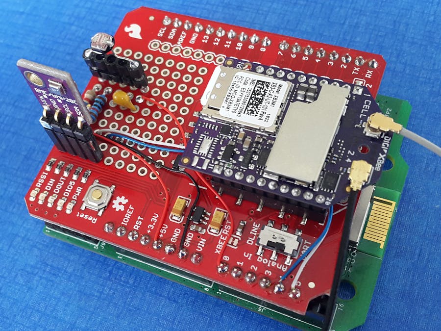
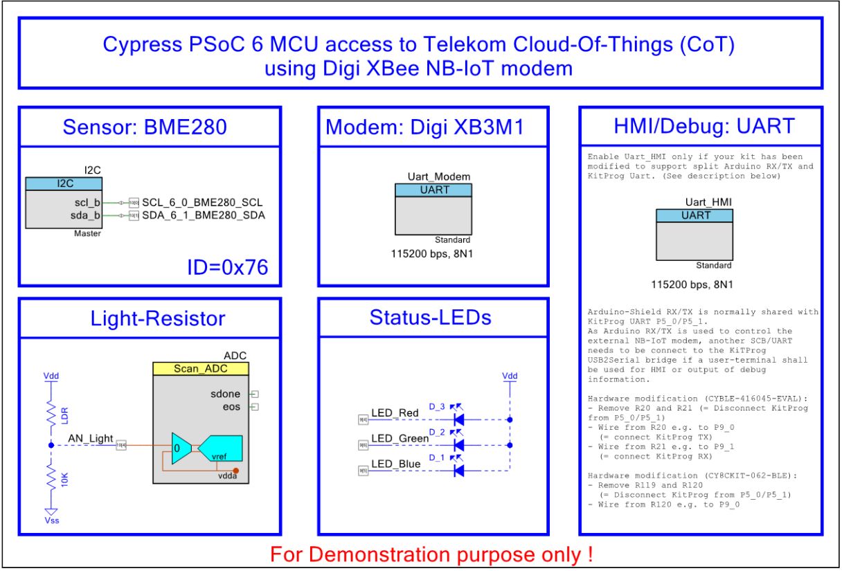
Target of that demonstrator is to realize a sensor node that publishes its data into the cloud so that it can be monitored all over the world. Cypress PSoC 6 MCU focus on low-power IoT applications, so also a related network system shall be used - Narrowband-IoT (NB-IoT). As shown in Figure 1 an environmental sensor is connected via the I2C interface for getting the temperature, relative humidity and barometric pressure. Another just simple light resistor is sampled by the ADC. These are the data sources of the demonstrator system.
The data is published into the Cloud-of-Things (CoT) offered by Deutsche Telekom and can be accessedby the provided web-interface where a dedicated dashboard was designed for the demonstrator.
Obviously, this is just an example demonstrator - the data source respectively types ofsensors, and cloud system can be adapted according to the user’s requirements.
Hardware modificationThe external XBee modem is connected via UART to the main controller (here: PSoC6MCU). Unfortunately, but caused by the Arduino specification, the USB-2-Serial bridge (CY KitProg) is connected to the UART pins reserved on the Arduino shield (TX0/RX0). That makes it uncomfortable if the user likes to use the USB-2-Serial connection for HMI and/or debugging purpose while using a shield that requires the UART connection, too. See Figure 2.
Therefore, the following hardware modification is proposed, to unfreeze the UART (port 5.0/5.1) from the KitProg USB-2-Serial converter. As shown in Figure 3 the KitProg will finally be connected to (port 9.0/9.1).
The modification obviously depends on the used development kit and needs only to be done if the application software requires a second UART.
Hardware modification of CYBLE-416045-EVAL
- Remove R20 andR21
- Wire R20/R21pad to J5 pin 7 and 6 (9.0/9.1).
Hardware modification of CY8CKIT-062-BLE:
- Remove R119 and R120
- Wire R119/R120 pad to J2 pin 2 and 4 (9.0/9.1)
One advantage of using a Digi XBee module is that it has already a kind of application firmware inside that takes over the connection process. After the module is configured correctly including the specification of the APN the user has not to take care of the low-level protocol but can use high-level API for the communication. After the module is powered it automatically tries to connect to the specified Access-Point-Name.
If the module is successfully connected, what can be verified by a user command (‘AI’), the communication to the cloud can take place by using MQTT-SN commands. After CONNECTing and REGISTERing the sensor data can be PUBLISHed.
As mentioned above the XBee modem comes with some firmware integrated that supports several use cases. The well-structured online documentation gives step-by-step instructions on the configuration, hardware information and supported commands. Unfortunately, no NB-IoT example is provided but at least a page for the configuration is available that explains the required settings for Europe and US.
For the configuration of the module the dedicated software tool XCTU is available here. It requires to have a serial connection e.g. by a USB-2-TTL bridge to the XBee module. The pinout description shows the relevant signals.
Ensure that the modem keeps the latest firmware (1140C or newer) inside otherwise a firmware update is necessary to use the NB-IoT protocol. Digi provides online guidance to update the firmware by help of the XCTU tool.
The Digi XBee modem is originally delivered with configuration for LTE-M. Ensure that you have the latest firmware running (NB-IoT was implemented by 1140C, what I have used in this demonstration). Within the online documentation a step-by-step guide is given how to configure NB-IoT. Remember, NB-IoT requires a cloud provider - so you need the APN details for correct configuration, e.g. Telekom nb-cloud.ic.m2mportal.de.
Alternatively I have added the.xpro configuration file of my setup what can be loaded by the XCTU configuration tool. Set the APN, in the AN field, type the APN value from your carrier and click the Write button.
The XBee Smart Modem supports three operating modes: Transparent operating mode, API operating mode, and Bypass operating mode. For this project the API mode is used, a frame-based protocol that allows a structured communication with the PSoC microcontroller. The API mode is recommended by Digi for most applications. The following table shows the related data frame structure in API mode: https://www.digi.com/resources/documentation/Digidocs/90002258/#Containers/cont_frame_descriptions.htm
The following section is an extract from the Digi documentation to give a rough summary of the API structure. Depending on the use case several frame data packages can be used.
For the given demonstrator two of it are mostly relevant, and the API-specific structure is shown in the following.
- ATCommand (0x08), At Command Response (0x88)Use this frame to query or set parameters on the localdevice.
- Transmit (TX)Request: IPv4 (0x20), Receive (RX)Packet: IPv4 (0xB0)Transmit data in IPv4 format, that is required for theNB-IoT connection. A TX request frame for a new destination creates a networksocket. After the network socket is established, data from the network that isreceived on the socket is sent out the device's serial port in the form of aReceive (RX) Packet frame.
AT Command (0x08), At Command Response (0x88)
Use this frame toquery or set parameters on the local device.
https://www.digi.com/resources/documentation/Digidocs/90002258/#Reference/r_frame_0x08_cell.htm
A device sends this frame in response to an AT Command(0x08) frame. Some commands send back multiple frames.
https://www.digi.com/resources/documentation/Digidocs/90002258/#Reference/r_frame_0x88_cell.htm
In the following some examples are given. As each frame contains an individual Frame ID defined by the user, the command sequences may differ in the checksum value related to the chosen ID.
1.Example ‘Read Temperature (TP)’
The AT command ‘TP’ reads the temperature of the XBee Smart Modem in degrees Celsius. The temperature value is read in 8-bit two’s complement format. For example, 0x1A = 26 °C, and 0xF6 = -10 °C. The API frame looks like this:
The related API response frame looks like this:
The result 0x00 indicates a successful operation (OK). The current temperature value 0x0019 reflects 25°C.
2.Example ‘Airplane Mode (AM)’
When set, the cellular component of the XBee Smart Modem is fully turned off and no access to the cellular network is performed or possible.
Send API (AM=1):  7E 00 05 08 F1 41 4D 01 47   AM1
Response          7E 00 05 88 F1 41 4D 00 F8   OK
Delayed Response: 7E 00 02 8A 03 72            Unregistered fromnetwork
Send API (AM=0):  7E 00 05 08 F1 41 4D 00 78   AM0
Response:         7E 00 05 88 F1 41 4D 00 F8   OK
Delayed Response: 7E 00 02 8A 02 73            Registered with cellular network
3. Example ‘Force Reset (FR)’
The device responds immediately with an OK and performs a reset 100 ms later. Before resetting or rebooting the device the airplane mode should be entered to allow the cellular module to detach from the network.
Send API: 7E 00 04 08 99 46 52 C6
4. Example ‘Association Indication (AI)’
This command is important to verify whether the modem has successfully connected to the network. It reads the Association status code to monitor association progress. The following table provides the status codes and their meanings.
Send API (AI):  7E 00 04 08 01 41 49 6C AI
Response:       7E 00 06 88 01 41 49 00 2A C2    Status Code, e.g. Airplane mode
Modem Status (0x8A)
Cellular component statusmessages are sent from the device in response to specific conditions.
https://www.digi.com/resources/documentation/Digidocs/90002258/#Reference/r_frame_0x8A_cell.htm
Transmit (TX) Request: IPv4 (0x20)
Mandatory for the NB-IoT communication to the Cloud Server to transmit data in IPv4 format. ATX request frame for a new destination creates a network socket. After the network socket is established, data from the network that is received on the socket is sent out the device's serial port in the form of a Receive (RX) Packet frame. The following table shows the related data frame structure:
https://www.digi.com/resources/documentation/Digidocs/90002258/#Reference/r_frame_0x20.htm
Transmit (TX) Status - 0x89
This frame indicates the result of a transmit operation.
https://www.digi.com/resources/documentation/Digidocs/90002258/#Reference/r_frame_0x89_cell.htm
Receive (RX) Packet: IPv4 (0xB0)
Reception package of RF data on a network socket that was created by a TX request frame. The following table shows the related data frame structure:
https://www.digi.com/resources/documentation/Digidocs/90002258/#Reference/r_frame_0xB0.htm
The following logfile demonstrates the basic communication required for the NB-IoT demonstrator. (See also Figure 6 above.)
Connect to the network
After powering the Digi XBee modem will automatically connect to the network. The current connection progress can be observed by the AT command ‘AI’ and its response:
Send API (‚AI‘):  7E 00 04 08 01 41 49 6C         AT command ‚AI‘
Response:         7E 00 06 88 01 41 49 00 22 CA   Status ‘22’: Registering to network
Send API (‚AI‘):  7E 00 04 08 01 41 49 6C         AT command ‚AI‘
Response:         7E 00 06 88 01 41 49 00 00 EC   Status ‘00’: Connected to network
Connect to the Cloud-of-Things (CoT)
The communication with the CoT is based on the MQTT-SN protocol what needs to be packed into the API frame structure.
Transmit(TX) Request: IPv4 (0x20):
7E 00 29 20 01 AC 19 66 97 07 5B 00 00 00 00 1D 04 04 01 03 84 31 32 33 34 35 36 37 38 39 30 31 32 33 34 35 53 52 55 6B 52 64 35 48 69
Explanation:
7E 00 29 20 01                  API frame (‘7E’), length (‘0029’), and ID(‘01’)
AC 19 66 97 07 5B 00 00 00 00   Destination(‘172.25.102.151‘), Port (‚1883‘),
                                Source (‚0000’), UDP (‘00’), Options (‘00’)
1D 04 04 01 03 84               Length, MQTT-SN CONNECT (‘04’),
                                Cleansession (‘04’), ID (‘01’), Duration (900sec)
31 32 33 34 35 36 37 38 39 30 31 32 33 34 35    Client-ID:IMSI
53 52 55 6B 52 64 35 48                         Client-ID: Password
69                                              Checksum
ReceiveTransmit (TX) Status (0x89)
7E 00 03 89 01 00 75 Successful transmit, Packed ID ‘01’
Receive (RX) Packet: IPv4(0xB0)
7E 00 0E B0 AC 19 66 97 00 0007 5B 00 00 03 05 00 23
Explanation:
7E 00 0E B0                    API (‘7E’), len (‘000E’), RX Packet: IPv4 (‘B0’)
AC 19 66 97 00 00 07 5B 00 00  Source(172.25.102.151), Dest.-Port (‘0000’),                                Source-Port (1883), UDP (‘00’), Rsvd(‘00’)
03 05 00                       Length, MQTT-SN CONNACK (‘05’), Return code(’00’, okay)
23                             Checksum
Register a Topic
Before a value can be sent to the cloud its topic must be registered and a related ID is received.
Transmit (TX) Request: IPv4 (0x20):
7E 00 2D 20 02 AC 19 66 97 07 5B 00 00 00 00 21 0A 00 00 00 02 4E 42 49 6f 54 2F 31 32 33 34 35 36 37 38 39 30 31 32 33 34 35 2F 4D 45 53 2F 31 41
Explanation:
7E 00 2D 20 02 AC 19 66 97 07 5B 00 00 00 00   ID (‘02’), IPv4 (‘20’), Destination,
                                               Port, Source, UDP('00'), Options('00')
21 0A 00 00 00 02                              Length, MQTT-SN REGISTER (‘0A’),
                                               unused (‘0000’), Msg-ID (‘0002’)
4E 42 49 6F 54 2F 31 32 33 34 35 36 37 38 39   Topic:
30 31 32 33 34 35 2F 4D 45 53 2F 31            NBIoT/"AUTH_IMSI"/MES/1
41                                             Checksum
Receive Transmit (TX) Status (0x89)
7E 00 03 89 02 00 74 Successful transmit, Packed ID ‘02’
Receive (RX) Packet: IPv4 (0xB0)
7E 00 12 B0 AC 19 66 97 00 00 07 5B 00 00 07 0B 00 1F 00 02 00 F8
Explanation:
7E 00 12 B0                     API (‘7E’), len (‘0012’), RX Packet: IPv4 (‘B0’)
AC 19 66 97 00 00 07 5B 00 00   Source(=172.25.102.151), Dest.-Port (‘0000’),
                                Source-Port (=1883), UDP (‘00’), Rsvd(‘00’)
07 0B 00 1F 00 02 00            Length, MQTT-SN REGACK (‘0B’), Topic-ID (‘001F’),
                                Message-ID (‘02’), Return code (’00’)
F8                              Checksum
Publish a Topic
After the topic name has been registered at the CoT sensor values can be sent by its related topic ID. Depending on the settings, no answer might be given.
Transmit (TX) Request: IPv4 (0x20):
7E 00 15 20 00 AC 19 66 9707 5B 00 00 00 00 09 0C 00 00 1F 00 00 31 37 1F
Explanation:
7E 00 15 20 00 AC 19 66 97 07 5B 00 00 00 00   Destination, Port, Source, UDP, Options
09 0C 00 00 1F 00 00                           Length,PUBLISH (‘0C’), Flags (‘00’),
                                               Topic-ID (‘001F’), Msg-ID (‘0000’);
31 37                                          Value must be sent to CoT as text:
                                               e.g.: 0x11 = 17d -> “17”
1F                                             Checksum
A complete logfilesnapshot is given in Figure 9.
The software is created by Cypress' IDE PSoC Creator. The TopDesign shows the used peripheral. UART_HMI is optional, and only required to get some debug information.
The software project contains mainly four user files:
_user_config_.h
This files keeps some user and hardware specific defines that must be adjusted by the user related to the hardware configuration and NB-IoT access data (IMSI, Password) as well as the topics used for publishing the sensor data.
#define KITPROG_UART_MAPPED_TO_NEW_SCB (0)  // <-- '1' if hardware is modified
#define SIMULATION (1)                      // <-- '1' if no sensors are connected
#define HARDWARE_TEST (0)                   // <-- '1' if sensor shall be debugged
#define AUTH_IMSI "123456789012345"         // <-- Add your IMSI here
#define AUTH_PWD  "SRUkRd5H"                // <-- Add your Password here
#define TOPIC1 "NBIoT/"AUTH_IMSI"/MES/1"    // <-- Define your topic
#define TOPIC2 "NBIoT/"AUTH_IMSI"/MES/A"    // <-- Define your topic
#define TOPIC3 "NBIoT/"AUTH_IMSI"/MES/5"    // <-- Define your topic
#define TOPIC4 "NBIoT/"AUTH_IMSI"/MES/2"    // <-- Define your topic
main_cm4.c
System initialization and data processing (sensor data sampling and publishing) is initiated here. Incoming data from the modem triggers an interrupt that forces adding the data into a ring buffer. Also, the I2C routines that are required to get the environmental data from the BME280 are implemented in this module. Within the infinite loop the modem is initiated to publish regularly the latest sensor values.
modem.c
This module keeps a ring buffer including some helper functions for the incoming data. Functions are implemented to prepare the correct API frame format required by the modem as described before:
void XBeeSendApiAT(…)       // Send API AT frame to XBee mode
void XBeeSendApiIpv4(…)     // Send API IPv4 frame to XBee modem
uint32_tXBeeEvaluateApi(…)  // Decoding of incoming API frames
Instead of using a full-featured MQTT-SN implementation some simple functions help to prepare the correct data packages:
void MQTTSN_Connect(…)      // Send a MQTT-SN CONNECT command
void MQTTSN_Register(…)     // Send a MQTT-SN REGISTER command
void MQTTSN_Publish(…)      // Send a MQTT-SN PUBLISH command
void MQTTSN_Disconnect(…)   // Send a MQTT-SN DISCONNECT command
The MQTT specification(s) can be found here: http://mqtt.org/documentation
Finally, a statemachine is implemented to handle the individual states for connecting, registering and publishing:
void XBEE_EventHandler(void)
bme280.c
This module is provided by Bosch Sensortec together with bme280.h and bme280_defs.h, and includes the routines required for the communication with the environmental sensor.
Telekom Cloud-of-Things (CoT)The Cloud of Things is a cloud-based Software as a Service of Deutsche Telekom for remote device monitoring and data management. The web portal enables to view all registered devices and manage them remotely. The portal provides a dashboard for the graphical display of collected data, alarms or defined parameters (KPIs).
The home dashboard consists of widgets, which visualize data. It can be edited easily, i.e. you can add, remove or change the widgets shown.
Figure 10 shows the dashboard currently used for the demonstrator, different widgets are used for displaying the current temperature, humidity, pressure and light values. Each widget can beconfigured by the user.
A "Data pointgraph" widget shows values for a define period or within thelast minute, hour, or day. Temperature, Humidity and Air pressure are very static values, but the light resistor at least gives some ‘dynamic data’ (yellow curve), that allows to observe the sunset, usage of electric light, as well as opening of the windows shutter ;-)
Demo setupAs described in the hardware chapter the demonstrator, shown in Figure 11, is based on a PSoC6 kit (CYBLE-416045-EVAL) and the Digi XBee NB-IoT modem, and on top a Bosch BME280 sensor connected via I2C to the PSoC to get some data. Additionally, a Light-Resistor is used to observe the brightness.
The PSoC6 based NB-IoT demonstrator using Digi XBee modem was connected several days to Deutsche Telekom NB-IoT network and worked successfully.
Sensor values (temperature, relative humidity and barometric pressure, ambient light) were transmitted regularly to the Cloud-of-Things and could be observed on the CoT dashboard accessed by a web browser.
Using a Digi XBee modem with the API protocol makes the software handling much easier compared to a low-level implementation of the pure modem, e.g. u-Blox, Quectel, etc.
This project summary hopefully helps you to build your own NB-IoT node.
#END


_3u05Tpwasz.png?auto=compress%2Cformat&w=40&h=40&fit=fillmax&bg=fff&dpr=2)

Comments
Please log in or sign up to comment.