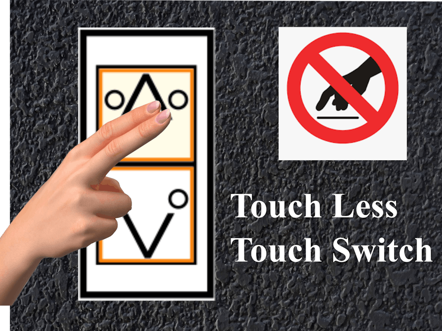
We all are now fighting against the prevailing COVID-19 pandemic. And also, now we are in a situation where we have to adapt to the prevailing conditions with more safety measures. While life coming back to normal with more safety measures to avoid virus infection, adding safety within the public places and crowded areas are also prevailing in the cities. But there were many situations where we have to break the safety measures and interact with an unsafe element to meet the needy. Here, the project is dealing with the prevention of COVID-19 spread though touch interactions or touches.
ATMs, Lifts, Vending Machines, etc are the places where a lots of people make use of those facilities. The chance of virus spread is very high in such places, where a lots of people indirectly comes into contact with other people through touches. The chance of community spread from those places is very high, since a single infected person can be a source of infection to a large number of people.
Thus the idea of the project is to build a touch free or a contact less User Interface for Public-Machine interaction. The idea is mainly concentrated over ATMs, Vending Machines, Lifts, etc were the public can't avoid touching and where the chance of Corona Virus spread is high.
Features- Touch less or contact free interactions.
- Easy to customize according the application.
- Cheap.
The hardware of the Touch less touch switch includes an Arduino Mega Board which serves as the main board or the controlling device of the project. Then comes the customized Touch Less Keypad - 01 and Touch Less Keypad -02. These boards severs the function of giving touch less inputs to the Arduino Board.
ArduinoMega is the micro-controller boards used to receive touch less inputs from sensor keys, process according to the code and execute the output.
Touch Less Keypad -01 is the primary input device which includes the number keys and basic control keys. The each and every key is incorporated with an IR LED proximity sensor used for locking the required keys instead of pressing. The proximity range of the IR LED can be varied according to the need. With the use of this keypad, the required key can be locked with two fingers waving or holding in front of the key for a particular time period (ex : 2 seconds) instead of pressing the buttons. The locking of the key will be indicated with a LED glow over the appropriate keys for a particular time period (ex : 5 seconds). Power adapters ranging from 12V to 5V can be used for powering up the boards.
TouchLessKeypad-02 is the secondary input device that can be designed according to the application of the device. Here it is designed accordingly, as if it's for the Lift control ( with UP and DOWN buttons ). All other specification and working are exactly same as that of the Touch Less Keypad - 01.
Note: Either any one of the Touch Less Keypad is only required to be powered, even though, power jacks are provided for both the boards.
How it works...?Whenever a finger ( or two fingers) is waved or held in front of the required key to be locked, for a particular time, then the key will get locked with a LED indication. As mentioned before, each keys are incorporated with IR Proximity sensors. So, in normal condition each and every sensor will give a HIGH input to the Arduino. But when ever a finger is held or waved in front of the sensor, the input from that sensor will goes to LOW. If the input continues the LOW state, the Arduino will compare the LOW state time period with predefined time and will lock the key with LED indication, if it matches. Any mismatch in time periods and state changes, will reset the sensors in the key. Then the locked key can also be unlocked by waving in front of the key again for a predefined time period. All other errors and invalid key locks can be rectified with a proper Arduino Code.
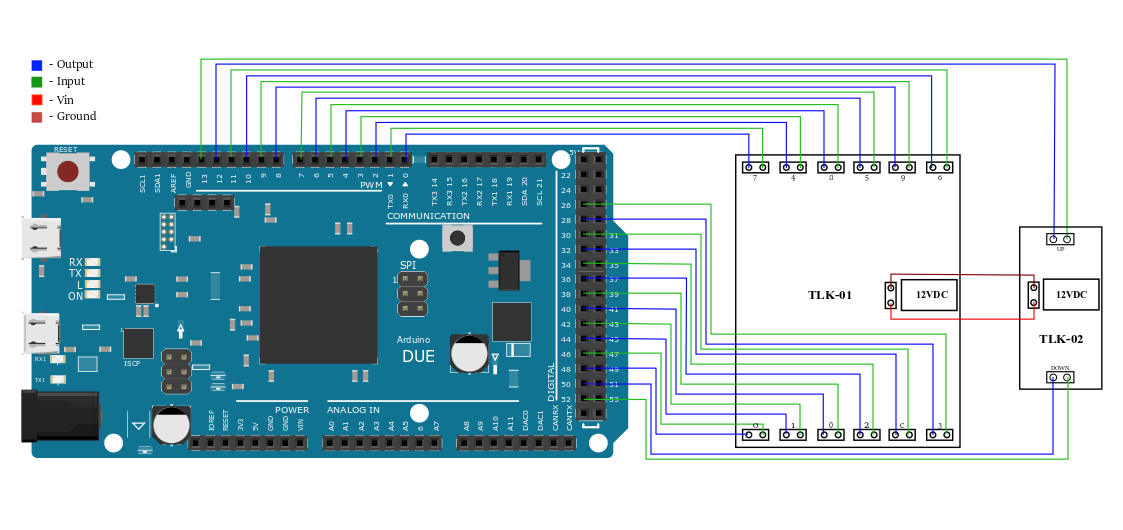
Build the circuit as per the given schematics. Use power adapters ranging from 5V to 12V for powering up the boards. Comparing with the schematics of the Touch Less Keypad, anyone can easily customize the schematics according to the application. The below schematics can be applied for touch less lift controlling system.
CodeThe basic Arduino program for the project is attached with this. Follow the below steps for flashing the code to the Arduino Mega board.
- Open Arduino IDE.
- Select File > New. Now a new window will be opening.
- Type or copy the given code.
- Save the sketch.
- Now connect the Arduino Mega Board to PC via a USB A to B cable.
- Then, select Tools > Board > Arduino/Genuino Mega or Mega 2560.
- Select Tools > Port. Now select the port to which the Arduino Board has been connected.
- Now compile the code and check for any errors by clicking the verify button. Rectify the errors, if any.
- Now upload the code to the Arduino Board by clicking the Upload Button.


_wzec989qrF.jpg?auto=compress%2Cformat&w=48&h=48&fit=fill&bg=ffffff)


Comments
Please log in or sign up to comment.