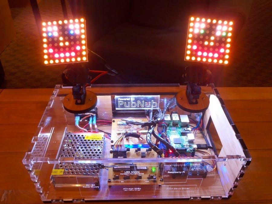
A demonstration of the PubNub realtime data streaming network and LeapMotion gesture recognition is going to be main goal of this project. There are plenty of demos involving applications or "push button here, LED on over there" type hardware, but we wanted to make something that was more interactive... a way to almost feel and manipulate the data stream. So, we decided to build a motion controlled "thing" that mimics your hand movements and displays colors based on finger positioning.
A conceptual overview and some more in depth look at some of the source code can be found on the PubNub blog, the complete source code is available in this GitHub Repo, and a separate project detailing the LED matrix driver circuitry has been written.
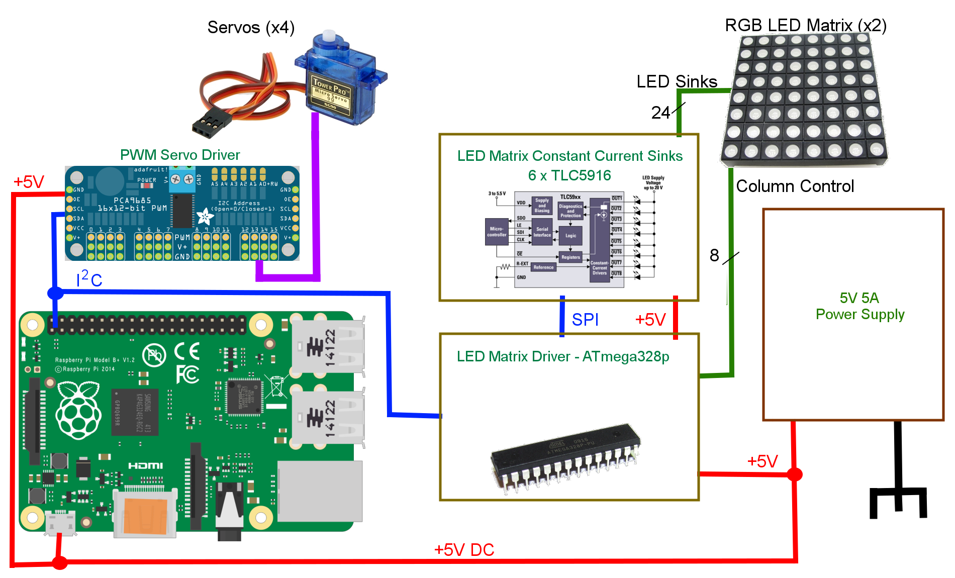
OverviewThe full project consists of two distinct parts: a user interface, and "the box." The user portion is a Leap Motion Controller running in the Java SDK. This program publishes data about the user's hand movements to the internet using PubNub. On the other side of the cloud, "the box" is subscribing to that data stream and responds accordingly. Inside the box, a Raspberry Pi is used to receive the data from PubNub and controls two servo rigs by way of an I2C enabled PWM driver. The RGB matrices are also controlled via the I2C bus and are based on the user's fingers.
In case you didn't understand that: hand movement data is published to the internet, and that data controls some servos and LEDs. That means the controller and box can be physically located separately anywhere in the world, as long as they are both connected to the internet! PubNub is the communications layer that makes the secure messaging work with minimal delay and high reliability.
Leap Motion is a powerful device equipped with two monochromatic IR cameras and three infrared LEDs. In this project, the Leap Motion is just going to capture the pitch and yaw of the user’s hands and publish them to a channel via PubNub. Attributes like pitch, yaw and roll of hands are all pre-built into the Leap Motion SDK.
To recreate realtime mirroring, the Leap Motion publishes messages 20x a second with information about each of your hands and all of your fingers to PubNub. On the other end, our Raspberry Pi is subscribed to the same channel and parses these messages to control the servos and the lights.
To work with Java, you will need a Java IDE and development kit on your computer. We used IntelliJ with JDK8. You will also need to install the PubNub Java SDK. The following imports are required at the top of the file and should not give any errors once you have all the proper libraries installed:
import java.io.IOException;
import java.lang.Math;
import com.leapmotion.leap.*;
import com.pubnub.api.*;
import org.json.*;
If you’ve never worked with a Leap Motion in Java before, you should first check out this getting started guide for the Leap Motion Java SDK.
It is crucial that you make your project implement Runnable so that we can have all Leap activity operate in its own thread. This is demonstrated in the java source code.
The Leap Motion captures about 300 frames each second. Within each frame, we have access to tons of information about our hands, such as the number of fingers extended, pitch, yaw, and hand gestures. The servos move in a sweeping motion with 180 degrees of rotation. In order to simulate a hand’s motion, we use two servos with one monitoring the pitch (rotation around X-axis) of the hand and the other monitoring yaw (rotation around Y-axis).
The values the Leap Motion outputs for pitch and yaw are in radians, however the servo driver is expecting a value between 150 and 600. Thus, we do some conversions to take the radians and convert them into degrees and then normalize the degrees into the corresponding PWM value.
Try running the program and check out the PubNub debug console to view what the Leap Motion is publishing. If all is correct, you should see JSON that looks something like this:
{
 "right_hand":{
                 "right_yaw":450,
                 "right_pitch":300
             },
 "left_hand":{
                 "left_yaw":450,
                 "left_pitch":300
             }
}
Now that the Leap Motion is publishing data, we need to set up our Raspberry Pi to subscribe and parse the retrieved data to drive and control the servos and LEDs.
Controlling Servos With A Raspberry PiOut of the box, Raspberry Pi has native support for PWM. However, there is only one PWM channel available to users at GPIO18. In this project, we need to drive 4 Servos simultaneously, so we will need a different solution.
Thankfully, the Raspberry Pi has HW I2C available, which can be used to communicate with a PWM driver like the Adafruit 16-channel 12-bit PWM/Servo Driver. In order to use the PWM Servo Driver, the Pi needs to be configured for I2C (to do this, check out this Adafruit tutorial).
Don’t worry about having the Adafruit Cobbler, it’s not needed for this project. If you do this part correctly, you should be able to run the example and see the servo spin. The program needs to do the following things:
- Subscribe to PubNub and receive messages published from the Leap Motion
- Parse the JSON
- Drive the servos using our new values
To start, the Raspberry Pi needs to be setup with the PubNub Python SDK, and must be able to connect the internet by way of a local Ethernet connection or a USB WiFi adapter. Also note that an external 5V power source for the servos is required. The Raspberry Pi can’t supply enough power to all four servos, so an external source needs to be used.
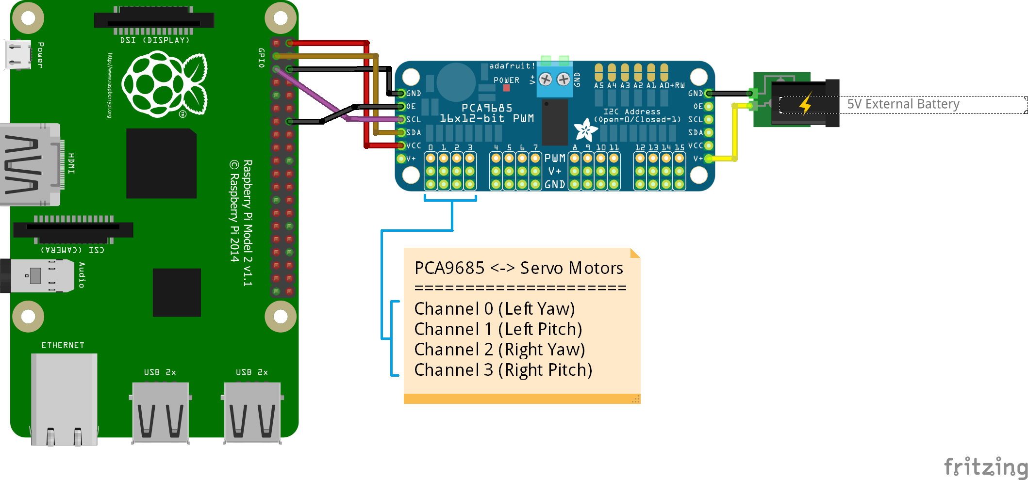
In this diagram, we attached a servo to channel 1 of the PWM driver. In the project, set up the servos like so:
- Channel 0 is Left Yaw
- Channel 1 is Left Pitch
- Channel 2 is Right Yaw
- Channel 3 is Right Pitch
Checkout the Pi source code in the project repo for more information.
Controlling RGB Matrix is another story and is not part of this project. Refer this project to get in-depth knowledge for Arduino RGB Matrix project.
In addition to the servo and matrix drivers on the I2C bus, the Pi has a reboot/shutdown button and drives some additional LEDs. A simple push button on the back of the box is used to signal the OS to shutdown or reboot. This is very important and helps to prevent SD card failure from interrupt write cycles as well as brown damage to the chips - the Pi is a micro computer after all! Holding the button for a second will turn an RGB LED blue to indicate a reboot, while holding the button for three seconds will turn the LED red to signal a shutdown. Check out the python script for more information.RPi2 Connection with PCA9685
Aside from that, an array of blue LEDs is used inside the box to indicate a successful connection to the internet. The Pi turns on these LEDs by way of a transistor in the PubNub subscribe on_connect callback. See the full python code for more information.
Lastly, we want these python scripts to run on boot, so we have to modify a special Linux file in the Pi's system. This can be done by adding a few lines to the /etc/rc.local file using elevated privileges, so...
> sudo vi /etc/rc.local
Just before the last line "exit 0", add a command to run the scripts. In this case, it is...
python
/home/pi/servo.py &&
python
/home/pi/shutdown.py &&
exit 0
Save the file and exit. The "/home/pi/" part is just the directory containing the python scripts. Make sure to include the "&&" parts or your Pi will never exit rc.local to start the Bash terminal!
Building the Servo RigsOur cheap micro servos came from Amazon. There are typically good deals on packages of 10 or more servos, but much high quality servos do exist and should be used if trying to move around anything heavier than our LED matrices.
The aluminum components that hold the servos are machined by a company called Lynxmotion. We used a few sets of these micro servo mounts, but I did have to bend them around a bit to fit our servos as these Tower Pro micro servos are a bit smaller than the micro servos these mounts were designed for.
One servo sits upright to rotate the entire matrix back and forth, the second is mounted on top of the base to change the matrix pitch. The result is a servo rig which can mimic most of a wrist's movements; however, a third servo would need to be added in order to mimic a wrist's ability to rotate, adding a third degree of freedom to the rig.
Wrapping UpWe wanted to put this project in a pretty package, so we whipped up a few vector image files, and sent them to local laser cutting company Ponoko. After the pieces got back, I had to trim a few edges that didn't quite fit how we liked as well as cut some additional holes for the power supply inlet, reset button, and LEDs. Building this box was not necessary, but it sure works better than a piece of cardboard!
That pretty much does it. This is a fun project to build, but it is only a small demonstration of what any of the individual components is actually capable of. I would love to see what you are able to come up with, so let me hear about it!


Comments
Please log in or sign up to comment.