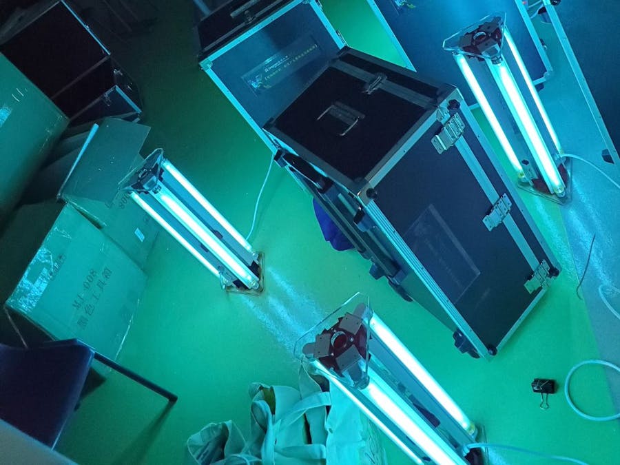
This ultraviolet germicidal light was designed by the Lingnan Entrepreneurship Initiative at Lingnan University to enable the disinfection of low-income housing in Hong Kong. Volunteers from local non-governmental organizations used the lights to disinfect over 1000 low-income residences in Hong Kong during the height of the COVID-19 pandemic. The lights were designed to be safe, durable and easy to use. The project was a collaboration between Lingnan University, Department of Social Work and Social Administration of The University of Hong Kong, Caritas Youth and Community Service, and Health In Action and funded by the Hong Kong Jockey Club Charities Trust. More information can be found here: https://www.ln.edu.hk/lei/events/project-ultra-violite
Important safety informationThis project presents risks from using AC mains power, as well as ultraviolet light in the C band.
Using and interacting with mains power is dangerous. The wiring in this project should only be done by someone trained in and comfortable working with mains power. If you are not familiar with the safety requirements of AC mains power, request assistance from a properly trained technician.
Ultraviolet light in the C band is harmful to the eyes and skin. Exposure can lead to blindness and burning. Never operate the lights in a way where you or other living things could be exposed to the light in any way. You must ensure that no one is in the same room as the lights, or in any location where they could be exposed to the lights while they are operating. This project provides a method to control the lights remotely through walls and doors using a remote control outlet. You may also consider controlling the lights through Bluetooth, as described in our other tutorial https://www.hackster.io/lingnan-entrepreneurship-initiative/bluetooth-control-for-uv-c-disinfection-lights-030e55
The MaterialsThe lights use commercially available fluorescent light fixtures and tubes, along with 3D-printed brackets to hold them together. Let's go over the details of the parts needed to make the lights:
- Marble MF3120 Fluorescent Light Fixture - we used these fixtures, but any T8 sized fluorescent light fixture could be used for this project. However, if you choose to use another light fixture, you would need to design and print your own 3D brackets.
- Sankyo Dinki G20T10 UV-C Germicidal lights. These are 20W fluorescent UV-C lights which produce light centered at 254 nanometer.
- StandardFluorescentLights. For testing the lights before using the harmful UV-C germicidal lights.
- Philips Eb-Ci Electronic ballast. This is an electronic ballast which provides the appropriate voltage and current to the fluorescent lights. It includes a built-in starter. Compared to standard magnetic ballasts, it is significantly lighter and allows multiple fluorescent lights to be started and used at once.
- Flexible tubing (25mm and 3mm). This tubing will be used in high risk areas to protect the wiring from being broken by the metal light fixture. Any durable flexible tubing of the appropriate diameter will work. You will need about 10cm of each.
- PhottixP220Tripod. The light is designed to be mounted to this model of tripod to provide a stable stand and enable the UV light to reach high up locations. The light may work with other tripods, but this is not guaranteed. If you would like to use a different tripod, you may need to modify the included CAD files to suit your application.
- 433 MHz Remote Control Outlet. This is a common used component to switch on lights and other household objects remotely. May also be called remote control socket or smart outlet.
- 3D printed brackets. These are used to hold the fluorescent light fixtures together at the appropriate angle to ensure an effective area of disinfection. Details for printing are in the next section
Three brackets are needed to securely hold the light fixtures together. The STL files for the parts are located in the attachments section. You will need to print two Outer Mounts and one Center Mount before beginning the assembly. You can optionally also print the End Plates if you have a printer with a large enough build plate. If you choose to print these, you will need two of them. They can also be constructed from plexiglass, wood or other durable material.
Prints were done using Ultimaker 3, Ultimaker S3 and Ultimaker S5 3D printers. We found good results using the following settings:
Material: Ultimaker Tough PLALayer height: 0.2mmInfill: 50%Rafts: NoneSupports: None
AssemblyIf you are using the Marble MF3120 or a similar fluorescent light fixture, you will first need to remove the included magnetic ballast, starter, and associated wiring from each light fixture. Also remove the cable protection glands and power cable from each. Retain one cable gland and one power cable for later use.
Next, connect two of the light fixtures using the Center Mount (the triangular shaped 3D printed piece). The fixtures are attached to the mount by inserting a M6 bolt through the hole in the light fixture shown with a red circle below, and screwing it into the corresponding hole in the Center Mount.
The resulting assembly should look as in the picture below. From now on, we will refer to the bottom fixture in the picture as Alpha, and the top fixture in the picture as Beta. The third (unpictured) fixture will be called Gamma.
We will now install the Philips electronic ballast into Alpha. To install, insert an M3 bolt from the back of the light fixture through the mounting hole on the ballast. It will go through the hole in the light fixture shown in the picture below, which is directly below the large hole in the fixture. Secure it with a nut.
Install the large flexible tubing, the one with a 25mm diameter, between Alpha and Beta. It should be about 7 cm in length. Install it through the large holes outlined in red in the photo above. The result should look as in the photo below.
Now install the Outer Mounts between Alpha and Beta. These are installed in the same way as the Center Mount, by inserting the M6 bolt into the hole in the fixture and screwing it into the mount. The hole for the Outer Mounts is the one directly below the U-shaped opening in the fixtures, as shown in the picture below.
After mounting, the two fixture should look as below
We will now focus on the wiring. It will be important to define the top and bottom of the lights, so we will define them as in the picture below
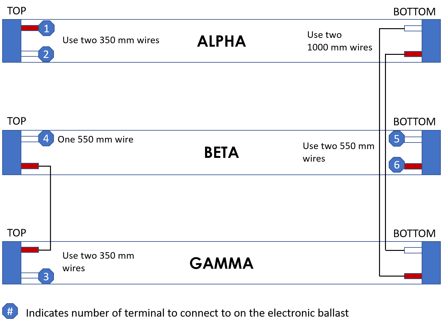
For a visual reference, you may use the schematic in the Attachments section.
To start, cut two lengths of wire, 350mm each. Strip about 10 mm of insulation off each end. Insert one end of each of these wires into the terminals labeled '1' and '2' on the ballast. Connect the other side of the wires to the connector at the top of Alpha. It does not matter which side of the connector each wire goes into, the connector is not directional. Congratulations, you have made your first connections!
Now cut two more lengths of wire, these ones 1000mm each. Strip about 10 mm of insulation off each end. Connect these to the connector on the bottom of Alpha. Again, it does not matter which side of the connector these go into. Run these wires through the large flexible tubing installed in the holes of Alpha and Beta. They will be attached to Gamma once it is installed.
Next, connect Gamma to the brackets in the same way that Alpha and Beta were connected using the remaining M6 bolts. Install the small flexible tube between Beta and Gamma using the small holes at the top of the fixtures as in the picture below.
Now pull the two 1000mm wires through the small flexible tube from Beta to Gamma. Connect these to the bottom connector of Gamma.
Cut and strip two 350mm wires and connect them to the top connector of Gamma. Run these two wires through the small flexible tube into Beta. Connect one of these wires to the top connector of Beta. Run the other one through the large flexible connector from Beta into Alpha. Connect this wire to terminal '3' on the electronic ballast.
To finish the wiring, return to Beta. Cut three wires to 550mm and strip them. Connect one to the remaining open position on the top connector of Beta. Connect the other two to the bottom connector of Beta. Run the wire from the top of connector through the large flexible tube into Alpha, and connect it to terminal '4' on the electronic ballast.
Run the wires from the bottom of beta through the large flexible tube into Alpha and connect them to terminals '5' and '6' of the electronic ballast. Congratulations, you have completed the most complicated portion of the wiring!
Finishing upNow all that is left is to provide power to the ballast. First, install a cable protection gland in the hole in the side of the Alpha fixture, as in the picture below.
Tighten it securely. Take one of the power cables removed from the fixtures at the beginning of the assembly and run it through the cable protection gland. Take the 3-way terminal strip and connect each wire from the power cable to the terminals on one side of the strip. Connect the live wire (brown) to the left-most terminal. Connect the neutral wire (brown) to the center terminal. Connect the ground wire (green/yellow) to the right-most terminal. Cut and strip two lengths of wire about 5 cm long, and one length of wire about 7 cm long. Use the 5cm wires to connect the live and neutral terminals to the appropriate connections on the electronic ballast. Use the 5 cm wire to connect the ground wire to the appropriate connection on the ballast. In the picture below, ground is the top-most connection point on the ballast.
Ensure all the connections are secure and cannot be easily pulled out. Then clamp the cable gland securely to the cable by twisting the outer nut clockwise. Ensure that the cable cannot move in the gland.
Finally, install the End Plates. The CAD files are at the end of the article. Using these CAD files, the End Plates can be 3D printed with a large enough 3D printer, but also can be fabricated from plexiglass or wood. To install them, use the M6 through the holes in the End Plates into the holes on the tops of the Outer Mounts.
Now reinstall the covers on the light fixtures. To test the lights, use normal lights, not the ultraviolet germicidal tubes! Install the tubes by putting the pins into the connectors, then rotating the bulbs until the click. The lights will not illuminate unless all tubes are installed. Plug the lights into an outlet and turn them on.
To operate with the Ultraviolet tubes, install the tubes in the same fashion as the normal fluorescent tubes. Do not plug the lights directly into the wall. Rather, plug the lights into the remote control outlet first. Then plug the remote control outlet into the wall outlet. Ensure there are no living organisms in the room, or near any windows of the room. LEAVE THE ROOM. When outside the room, turn the lights on using the remote for the remote control outlet. You can monitor the function of the lights using a UV meter or camera. If you wish to use a Bluetooth application, see our other tutorial: https://www.hackster.io/lingnan-entrepreneurship-initiative/bluetooth-control-for-uv-c-disinfection-lights-030e55


Comments
Please log in or sign up to comment.