


Hardware components | ||||||
 |
| × | 1 | |||
 |
| × | 1 | |||
| × | 1 | ||||
| × | 1 | ||||
 |
| × | 1 | |||
| × | 1 | ||||
| × | 1 | ||||
 |
| × | 1 | |||
 |
| × | 1 | |||
| × | 1 | ||||
| × | 1 | ||||
Software apps and online services | ||||||
| ||||||
| ||||||
 |
| |||||
 |
| |||||
| ||||||
Hand tools and fabrication machines | ||||||
 |
| |||||
 |
| |||||
| ||||||
| ||||||
Pachamama is the ancient Andean God of earth and time. Also known as mother earth she watches over the plants and harvests. As a tribute to her, nature, and the Spring I created this tutorial to show how the Internet of Things can be used in extremely practical ways that help illustrate how amazing the world around us is.
This project will be broken up in 5 parts: the circuit, the code, the Hologram cloud routes to SMS and Losant, the enclosure, and the end result.
The circuit for the Pachamama Plant Monitor consists of a DHT11 temperature and humidity sensor and a moisture sensor combo made by OSEPP called the MHUM-01. Nevertheless, the same results can be achieved using a stand alone DHT11 and a moisture sensor. On top of this there is a photo-resistor + 20 Ohm resistor voltage divider circuit to act as a light sensor and a common anode RGB LED that acts as a status indicator.
*Note that there is an alternate configuration that allows users to only power our MHUM-01 when we take sensor readings, thus saving power for remote deployments and also reducing the moisture sensor's up-time to avoid corrosion. Enabling this simply requires one to plug the sensor's power pin to pin D12 on the Dash which is the sensorpower pin in our code. For those looking to make this a low power, battery driven device I would recommend looking at the Dash's power saving and battery management functions.
The code for our project can be broken up into 5 sections. These are the Instantiation and Declaration section, the Setup section, the Moisture function, the JSON function, the ConectionStatusLED function and the Main Loop section.
Instantiation and Declaration
The Instantiation and Declaration section is fairly straight forward, but sets the stage for the rest of the code so lets go over it in some detail. The first thing we do is include Adafruit's DHT library (Shout out to Adafruit). Note that our OSEPP MHUM-01 has a built in DHT 11 which is why this library works. Otherwise, if you don't have the MHUM-01, you can simply replace it with a regular analog soil moisture sensor and a DHT 11 and the code will still work (the circuit might need a minor tweak).
We then proceed to define the pin we use for our DHT sensor, as well as the sensor type, given that this library also works for the DHT22 and a few other sensors. Lastly we instantiate the DHT object. Below that subsection we declare our external RGB LED pins as well as the moisture and light sensor.
Below that, we declare our auto topic customization variables. These allow us to run this code on multiple devices and get unique topics from each based on the SIM Number (ICCID); thus making it easier to manage them in the Hologram Dashboard. After that, we declare the remaining variables: the (rough) delay between messages, the timekeeping variable, and a moisture dummy value.
The last part of this block is the sensorpower pin. As explained in the circuit section this pin is meant to allow users to only power our MHUM-01 when we take sensor readings,. This saves power for remote deployments and also reduces the moisture sensor's up-time to avoid corrosion. Enabling this simply requires one to plug the sensor's power pin to pin D12 on the Dash and un-commenting the relevant lines of code.
#include <DHT.h> //include the DHT library
#define DHTPIN D14     // DHT Sensor output pin connected to Dash GPIO
#define DHTTYPE DHT11   // DHT 11
DHT dht(DHTPIN, DHTTYPE); //DHT Settings
//Declare RGB LED Pins
int blue_led = D15;
int green_led = D16;
int red_led = D18;
//Declare Other Sensors
int moisture_sensor = D13;
int light_sensor = D19;
//Declare Auto Topic Customization
String ICCID = "ICCID";
String WateredTopic = "Watered_";
String ThirstyTopic = "Thirsty_";
String PachamamaTopic = "Pachamama_";
//Declare
int delay_to_send = 300000; //delay between sending messages
unsigned long previousMillis = 0; //initialize timekeeping
int moisture = 100; //Set Moisture Value Dummy
//int sensorpower = D12; //optional power for the probe to avoid corrosion uncomment if you want to use the sensorpower pin
Setup
In the Setup section we get this show on the road. We start by setting the pinmode for all our output pins. After that there is a quick boot sequence that runs through the external RGB LED's pins to double check that they are all plugged in correctly. We then personalize the device's topics by getting the SIM's number (ICCID), breaking it down to its last four digits, and concatenating them to our topic variables. Lastly, we initialize communications with the DHT sensor.
Once the internal heavy lifting is done we shift focus to communication. We start by whipping up serial communications with the classic baud rate of 9600. To test this, we send the string "Start". Next, we establish communications with the Hologram cloud by sending a "Starting" message with the customized Pachamama topic. We then take a break for biscuits and Tea 🎩☕️🍪 *Cheers* and resume by sending our first data package!
void setup() {
 pinMode (blue_led, OUTPUT);
 pinMode (green_led, OUTPUT);
 pinMode (red_led, OUTPUT);
 pinMode (sensorpower, OUTPUT);
   //Boot sequence
 digitalWrite (blue_led, HIGH);
 delay(1000);
 digitalWrite (blue_led, LOW);
 digitalWrite (green_led, HIGH);
 delay(1000);
 digitalWrite (green_led, LOW);
 digitalWrite (red_led, HIGH);
 delay(1000);
 digitalWrite (red_led, LOW);
 digitalWrite (green_led, HIGH);
 //Personalize Topics for Multiple Devices
 ICCID = HologramCloud.getICCID();
 ICCID = ICCID.substring(14);
 WateredTopic.concat(ICCID);
 ThirstyTopic.concat(ICCID);
 PachamamaTopic.concat(ICCID);
 dht.begin(); //Initialize DHT object
 //Establish Communication via Serial and the Hologram Cloud
 Serial.begin(9600);
 Serial.println("Start");
 HologramCloud.sendMessage("Starting", PachamamaTopic);
 delay (3000);
 moisture = Moisture();
 Serial.println(JSON(moisture));
 HologramCloud.sendMessage(JSON(moisture), PachamamaTopic);
}
Moisture Function
The moisture function is used to get our sensor's moisture value and it is pretty straight forward. We take the analog reading and map the values to something between 0 and 100. My upper and lower bounds during testing were 100 and 575, but I suggest you run your own tests as this can vary depending on the sensor and soil composition. After that we constrain these values to make sure that our future integrations don't run into unexpected errors. Lastly, we return the moisture value. For those using the sensor power pin, you'll want to uncomment the three lines below.
//Getting and Mapping Moisture
int Moisture () {
 //digitalWrite (sensorpower, HIGH); //uncomment if you want to use the sensorpower pin
 //delay(10); //uncomment if you want to use the sensorpower pin
 moisture = analogRead(moisture_sensor);
 moisture = map (moisture, 100, 575, 0, 100);
 moisture = constrain (moisture, 0, 100);
// digitalWrite (sensorpower, LOW);  //uncomment if you want to use the sensorpower pin
 return moisture;
}
JSON Function
The JSON function gets the values from all our other sensors and formats them, along with the moisture sensor value, into JSON (JavaScript Object Notation). Having our information in JSON will make integrating with other services over the web much easier. To do so, we start by creating an 8-bit character that will be used for our sensor values. We then get the light value and like the moisture value from the function above we map it and constrain it.
We then start building our JSON by converting our values to strings using the dtostrf() function. This is an AVR function that takes the variable to manipulate, a minimum string length, the numbers after the variable's decimal, and a variable to store our result in and spits out a neatly formatted string. This string, buf, is appended to our first variable name "moisture :" which includes our JSON's opening curly brackets and "\" to make sure the quotation marks are escaped. We then add a comma to separate the key value pairs and rinse and repeat for our other sensor values. For temperature and humidity we use the DHT library's readTemperature() and readHumidity() functions, and finish our data payload off with a closing curly bracket.
//Getting, Mapping, and Formatting our Data in JSON
String JSON(int moisture) {
 char buf[8];
  //digitalWrite (sensorpower, HIGH); //uncomment if you want to use the sensorpower pin
 //delay(10); //uncomment if you want to use the sensorpower pin
 int light = analogRead(light_sensor);
 light = map (light, 500, 1023, 0, 100);
 light = constrain (light, 0, 100);
 dtostrf(moisture, 4, 2, buf);
 String ret = "{\"moisture\":";
 ret.concat(buf);
 ret.concat(", ");
 dtostrf(light, 4, 2, buf);
 ret.concat("\"light\":");
 ret.concat(buf);
 ret.concat(", ");
 dtostrf(dht.readTemperature(), 4, 2, buf);
 ret.concat("\"temp\":");
 ret.concat(buf);
 ret.concat(", ");
 dtostrf(dht.readHumidity(), 4, 2, buf);
 ret.concat("\"humidity\":");
 ret.concat(buf);
 ret.concat("}");
 //digitalWrite (sensorpower, LOW);  //uncomment if you want to use the sensorpower pin
 return ret;
}
ConectionStatusLED function
The connectionStatusLED() function is used to check our device's connection and both send a message via serial communications as well as change the color of the Dash V1.2's onboard RGB LED. To do this, we use the Dash's isConnected() function inside the conditional portion of an if statement. If the device is connected we append the word good to a string that reads "Connection status is: ". We also set the onboard RGB LED to green. Otherwise, we append the word bad to our string and set the RGB to red.
*If you are using an earlier version of the Dash you'll need to add an RGB LED and massage our code to get this part to work.
//Conection Status FN that changes the onboard LED and returns a connection status string
String connectionStatusLED() {
 String ret = "Conection status is: ";
 if (HologramCloud.isConnected()) {
   ret.concat("good");
   HologramCloud.setRGB("GREEN");
 }
 else {
   ret.concat("bad");
   digitalWrite (red_led, HIGH);
   HologramCloud.setRGB("RED");
 }
 return ret;
}
Main Loop
The main loop is the portion of our code that will repeat and where all the functions discussed above come together. The first thing we do is check the status of our connection using the connectionStatusLED() function placed inside a print statement to make sure we get the status on our serial monitor in addition to the LED change. We then pause for 10 seconds and turn the RGB LED off followed by a one second delay. We do this because the rest of the code runs so fast that the timing around the section above will control the onboard LED's behavior and we want to leave it on long enough to see that status, but also blink it to easily determine that our code is still running.
After this we check to see how much time has passed using a variable called currentMillis and comparing it to our previousMillis value. Doing this as opposed to using delays allows us to run code during the down time which enables us to constantly check connection status instead of having to tie it to whatever time period we want to elapse before we send out our messages. In other words this allows us to run code while we wait for the time to pass to send out our sensor values.
If the time that has passed is longer than our delay then we set the moisture value to the output of our Moisture() function and then use that value in an if statement that determines if our plants are watered or thirsty.
If the plants are watered we send out the sensor values with our Watered topic. We then turn off all the external RGB LED's leads and power the one that will light it up green. If the plants are thirsty we do the same thing except that we send the Thirsty topic instead of the Watered one, and we light the external RGB LED blue.
Lastly, we send our sensor values out via serial and update our time keeping variables by setting our previousMillis value to currentMillis.
void loop() {
   Serial.println(connectionStatusLED()); //Check Connection Status
   delay(10000);
   HologramCloud.offRGB();
   delay(1000);
 //check time to see if its been more than the delay value
 unsigned long currentMillis = millis();
 if ((unsigned long)(currentMillis - previousMillis) >= delay_to_send) {
   moisture = Moisture();
// Branch for watered plants
   if (moisture > 50) {
     HologramCloud.sendMessage(JSON(moisture), WateredTopic);
     digitalWrite (blue_led, LOW);
     digitalWrite (red_led, LOW);
     digitalWrite (green_led, HIGH);
   }
//Branch for Thirsty Plants
   else {
     HologramCloud.sendMessage(JSON(moisture), ThirstyTopic);
     digitalWrite (green_led, LOW );
     digitalWrite (red_led, LOW);
     digitalWrite (blue_led, HIGH);
   }
   Serial.println(JSON(moisture));
   previousMillis = currentMillis;
 }
}
Here is all the code in one block for your copy pasting pleasure:
#include <DHT.h> //include the DHT library
#define DHTPIN D14     // DHT Sensor output pin connected to Dash GPIO
#define DHTTYPE DHT11   // DHT 11
DHT dht(DHTPIN, DHTTYPE); //DHT Settings
//Declare RGB LED Pins
int blue_led = D15;
int green_led = D16;
int red_led = D18;
//Declare Other Sensors
int moisture_sensor = D13;
int light_sensor = D19;
//Declare Auto Topic Customization
String ICCID = "ICCID";
String WateredTopic = "Watered_";
String ThirstyTopic = "Thirsty_";
String PachamamaTopic = "Pachamama_";
//Declare misc. Variables
int delay_to_send = 300000; //delay between sending messages in ms
unsigned long previousMillis = 0; //initialize timekeeping
int moisture = 100; //Set Moisture Value Dummy
//int sensorpower = D12; //optional power for the probe to avoid corrosion uncomment if you want to use the sensorpower pin
void setup() {
 pinMode (blue_led, OUTPUT);
 pinMode (green_led, OUTPUT);
 pinMode (red_led, OUTPUT);
 pinMode (sensorpower, OUTPUT);
   //Boot sequence
 digitalWrite (blue_led, HIGH);
 delay(1000);
 digitalWrite (blue_led, LOW);
 digitalWrite (green_led, HIGH);
 delay(1000);
 digitalWrite (green_led, LOW);
 digitalWrite (red_led, HIGH);
 delay(1000);
 digitalWrite (red_led, LOW);
 digitalWrite (green_led, HIGH);
 //Personalize Topics for Multiple Devices
 ICCID = HologramCloud.getICCID();
 ICCID = ICCID.substring(14);
 WateredTopic.concat(ICCID);
 ThirstyTopic.concat(ICCID);
 PachamamaTopic.concat(ICCID);
 dht.begin(); //Initialize DHT object
 //Establish Communication via Serial and the Hologram Cloud
 Serial.begin(9600);
 Serial.println("Start");
 HologramCloud.sendMessage("Starting", PachamamaTopic);
 delay (3000);
 moisture = Moisture();
 Serial.println(JSON(moisture));
 HologramCloud.sendMessage(JSON(moisture), PachamamaTopic);
}
void loop() {
   Serial.println(connectionStatusLED()); //Check Connection Status
   delay(10000);
   HologramCloud.offRGB();
   delay(1000);
 //check time to see if its been more than the delay value
 unsigned long currentMillis = millis();
 if ((unsigned long)(currentMillis - previousMillis) >= delay_to_send) {
   moisture = Moisture();
// Branch for watered plants
   if (moisture > 50) {
     HologramCloud.sendMessage(JSON(moisture), WateredTopic);
     digitalWrite (blue_led, LOW);
     digitalWrite (red_led, LOW);
     digitalWrite (green_led, HIGH);
   }
//Branch for Thirsty Plants
   else {
     HologramCloud.sendMessage(JSON(moisture), ThirstyTopic);
     digitalWrite (green_led, LOW );
     digitalWrite (red_led, LOW);
     digitalWrite (blue_led, HIGH);
   }
   Serial.println(JSON(moisture));
   previousMillis = currentMillis;
 }
}
//Getting and Mapping Moisture
int Moisture () {
 //digitalWrite (sensorpower, HIGH); //uncomment if you want to use the sensorpower pin
 //delay(10); //uncomment if you want to use the sensorpower pin
 moisture = analogRead(moisture_sensor);
 moisture = map (moisture, 100, 575, 0, 100); //You will want to test your own upper (575) and lower (100) bounds here
 moisture = constrain (moisture, 0, 100);
// digitalWrite (sensorpower, LOW);  //uncomment if you want to use the sensorpower pin
 return moisture;
}
//Getting, Mapping, and Formatting our Data in JSON
String JSON(int moisture) {
 char buf[8];
  //digitalWrite (sensorpower, HIGH); //uncomment if you want to use the sensorpower pin
 //delay(10); //uncomment if you want to use the sensorpower pin
 int light = analogRead(light_sensor);
 light = map (light, 500, 1023, 0, 100); //You will want to test your own upper (1023) and lower (500) bounds here
 light = constrain (light, 0, 100);
 dtostrf(moisture, 4, 2, buf);
 String ret = "{\"moisture\":";
 ret.concat(buf);
 ret.concat(", ");
 dtostrf(light, 4, 2, buf);
 ret.concat("\"light\":");
 ret.concat(buf);
 ret.concat(", ");
 dtostrf(dht.readTemperature(), 4, 2, buf);
 ret.concat("\"temp\":");
 ret.concat(buf);
 ret.concat(", ");
 dtostrf(dht.readHumidity(), 4, 2, buf);
 ret.concat("\"humidity\":");
 ret.concat(buf);
 ret.concat("}");
 //digitalWrite (sensorpower, LOW);  //uncomment if you want to use the sensorpower pin
 return ret;
}
//Conection Status FN that changes the onboard LED and returns a connection status string
String connectionStatusLED() {
 String ret = "Conection status is: ";
 if (HologramCloud.isConnected()) {
   ret.concat("good");
   HologramCloud.setRGB("GREEN");
 }
 else {
   ret.concat("bad");
   digitalWrite (red_led, HIGH);
   HologramCloud.setRGB("RED");
 }
 return ret;
}
Now whats the point of automating your plant's vital sign measurements if you're not going to use the data to make your life easier?
Exactly! So, lets kick this project up a notch and use the Hologram Dashboard's Routes feature to send an SMS alert whenever our plants need to get watered and also graph all these metrics in a convenient dashboard.
SMS
The SMS route is surprisingly straight forward. We take advantage of the Topics we built into our code and Hologram's Heartbeat modifier. To do this we create an SMS route, select the Watered Topic, add a Heartbeat operation (which I set to 15 minutes), and enter our phone number.
Voilà, that was easy!
But Maiky, why don't we just use the Thirsty topic and omit the heartbeat operation?
Good question. The reason why we create the route this way is that we don't want to get a message every time we receive a thirsty message. If you don't have immediate access to your plants, or they need to be watered at night, this could get very annoying, very fast! Therefore, we take advantage of the fact that the heartbeat operation will alert you once, and only once, if it hasn't received the topic its looking for in the time frame before triggering the alert. Thus, after getting the thirsty text once, the system waits to get a new watered message before it sets up the next trigger.
Losant
Losant is a fantastic dash-boarding service that integrates seamlessly with Hologram's services making data visualization a cake walk.
In Losant, we kick things off by making an application and giving it a name. In the application we create a webhook where, again, all we do is give it a name. The webhook is the piece that will receive information from our Hologram Dashboard. Still in the same application we create a device, and this time we give it a name, a description, and Data Type values for Temperature, Humidity, Moisture, and Light, all under Device Attributes.
Once that is done we proceed to create a Cloud Workflow. After we give it a name we are taken to the workflow manager which is a graphical programing interface. Here, we wanna add a green "webhook" trigger connected to an orange "device state" output and an orange "debug" output. Next we click on the "Device State" Icon and set the Values for the Attributes in the State Section using the following formatting: {{data.body.variable}}.
Lastly, we click on the "Webhook" icon and copy the hook URL which will be used in the Route on the Hologram side.
Moving back to the Hologram Dashboard, we create a new Route, select the automatic device topic, and the Losant Webhook action. For the Webhook key you paste the final portion URL copied from the webhook section above. Saving this route means that we are officially sending data to Losant!
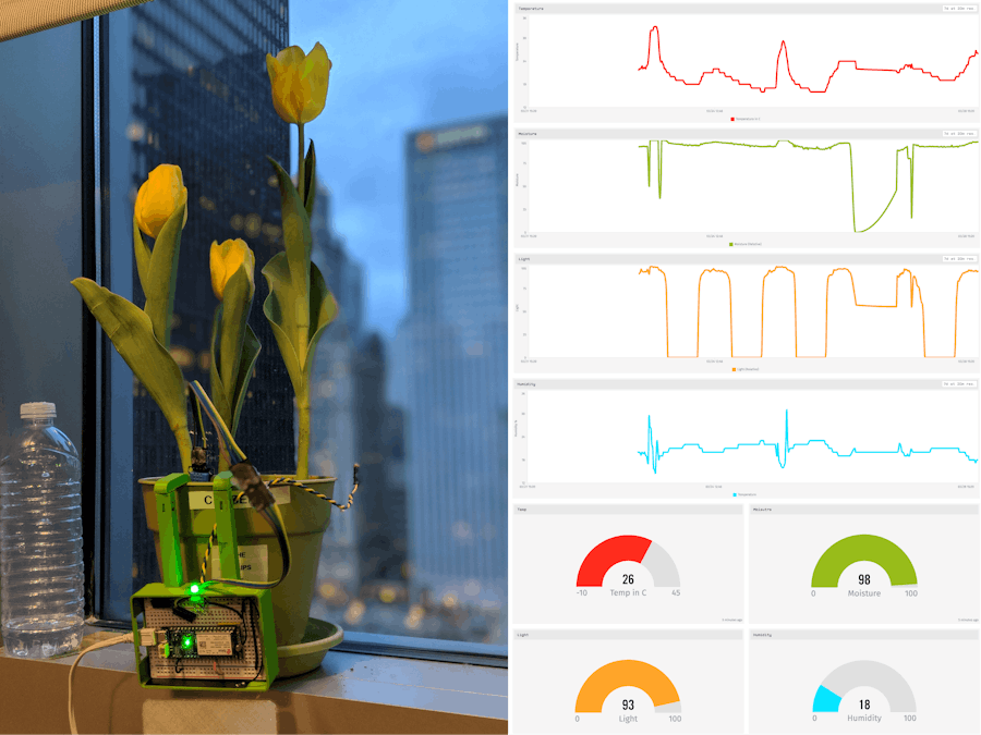
The last piece we want to take care of is the visualization portion in Losant. To do this, we go back to Losant and create a new Dashboard. For my Dashboard I created a Time Series Graph and a Gauge. The pictures below show the setup:
The final Dashboard looks like this:
The enclosure for this project was based on the box designed in this Layer by Layer YouTube tutorial and optimized to print without supports. To achieve this, the hooks that keep the enclosure on the pot have an internal mechanism that allows them to spin 360 degrees.
The main enclosure was printed with an Ultimaker 3 in green PLA and took 11 hours and 20 minutes at a 0.1mm layer height and 20% infill. The lid is made with transparent PLA so we can see the Dash's RGB LED and took 4 hours to print with the same settings.
To keep with the theme of Spring, we also have a flower model that fits the photoresistor.
Our flower was printed in orange PLA and took 30 minutes to print at 0.1mm layer height and 20% infill.
Like with every project, there was a ton to learn here and I couldn't have done it without guidance of Eric "Yoda" L., Ben L., Chris G., Chris S., Pranavacus Finch, and Franky R. Big shout out to all of you.


Comments
Please log in or sign up to comment.