If we knew how much energy we use at each moment, I am convinced that we would use it better, just for the pleasure of seeing the consumption metrics go down.
I verified this once I installed a screen showing the energy consumption of my house in the corridor. With the fact of announcing that the number with the W next to it, the bigger it was, the more expensive the bill would be at the end of the month, I already had my family turning off things, just to see it go down.
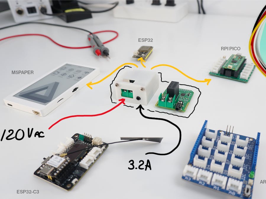
I've been making videos of power meters for a while now and I set out to create a metering module that we could easily use with any microcontroller.
If you are a visual learner I know that a video is worth more than 1000 words, so here is a tutorial video. (I am a Spanish speaker, so please consider turning on English subtitles):
The Hardware:You will need a development board and the DIY energy meter (see schematics and PCB files attached).
The module uses UART for communication, and has been tested with these boards:
- XIAO ESP32C3
- Raspberry Pi Pico.
- M5Paper (ESP32).
- Adafruit ESP32 Feather.
I designed the circuit in EasyEDA, using the available components (which are many) to also be able to request the assembled board from there, from the surface mount components and those that are not, all that remained to do was solder the white connector and the pins. (for saving).
Here we can see the diagram of this circuit, with this one I took a risk, because it was the first one I did looking only at the data sheet of the main chip, but if I'm making the video, it's because it went well.
We have, the current measurement stage where we will connect our CT, the voltage measurement stage, where we will connect the 120/240 V AC from the network, the IC is the one that does the hard work, and this is the point, that the measurement is not made by our microcontroller and that they only pass us the data. We have a voltage regulator, for when the board is going to be powered with 5V, which we define with this jumper, and finally, a Grove connector to make the module compatible with the Seeed Studio and Arduino ecosystem.
As for the PCB, I tried to give it a similar style to the Arduino UNO, but basically, the important thing here is to comply with the recommendations of the IC manufacturer, keep the filter resistors as close to the chip as possible, and have the high voltage AC area detached from the ground plane and the correct distance between tracks…for obvious reasons.
Do you want my advice for a personal or university project? Let me be your consultant.
This module does not need calibration, since the readings are defined by the individual components of the circuit, say resistors and transformers.
For example, if we look at the datasheet, with this configuration, that is, using CT and PT, the voltage is defined by this formula:
Where we have the array of resistors in series and the load resistance of the PT.
On the other hand, the current:
Apart from using the Burden resistance of 3.3 Ohms, also considers the ratio of turns of the CT, which in this case is 2000 to 1, so our Rt is 2000.
If this is respected, the measurements delivered by the module will be correct. But now, let's try this.
The enclosureAnd I'm going to make a super parenthesis to show you the little box I designed for the module, I also had it made at JLCPCB and wow, look at the quality.
JLCPCB 3D printing service starts from $1
I made a code for the ESP32, the ESP32C3 and the Raspberry Pi Pico, but they all have in common the declaration of the values of the resistors and the ratio of the CT since the formulas that I explained to you just now are used here. You, clone the repository and open the code of the board that you are going to use.
Here we are testing with the ESP32C3 and the expansion board from Seeed Studio.
We connect the AC cable for voltage measurement and hook up the CT of one of the load lines and that's it.
We have voltage, which we can validate, and that is perfect:
We have current, which we also validate, and uff, with a clamp or by measuring normal, perfect:
The power and here I stop, what allows us to measure real active power is the ability to consider the power factor and here we can validate it by applying the formula that W = I*V*cos(phi), and we see that it effectively gives me the correct value:
As you already know, a good meter should be able to measure power factor, which is only achieved if the voltage is measured to then determine the phase angle between the current and the latter.
This module has an interesting feature when we talk about measuring energy and that is that it has an output, like the meters in our houses, which makes an LED blink depending on the instantaneous power consumed, with each pulse the power is integrated giving us the energy value in kWh.
What can I say?, happy with the results I have obtained, and ready to create support for new boards for this module.


Comments
Please log in or sign up to comment.