#Notes at the beginning
Since we haven't released our SenseCraft firmware back in July, an open source software platform to build smart sensors with no-code, so I used a lot of configs during coding to make this system work(which is not applicable for now). So, if you want to replicate the project, please feel free to download the SenseCraft Firmware to give it a try, as I believe it can fulfill your needs.
SenseCraft delivers a complete out-of-the-box solution to sense the real-world, process data and send the data to the cloud in the easiest and fastest way possible with no coding experience at all! If you're planning to work on a smart farming proof-of-concept, please do check out SenseCraft which can help you build up the project in 3 steps on the SenseCAP K1100 Kit.
From July 10th to 20th, I was sent to an on-site event called ‘Dinacon 3’ - an event focused on wild hacking for nature as a Seeed Representative. Here I've conducted an AIoT2Wild Workshop using the SenseCAP K1100 Kit for 15 participants. Moreover, I also created a hands-on project with some other participants centering around Precision Agriculture. It was a great journey, and here I'd love to document my smart luffa farming project that I built on site.
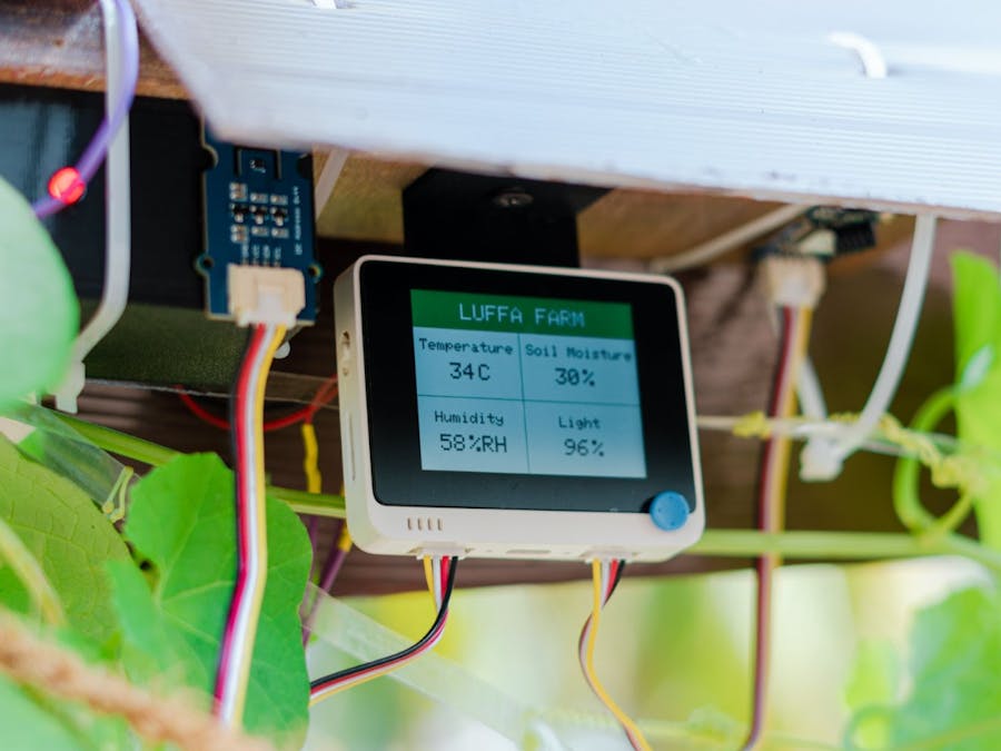
After scouting through the surroundings of DreamSpace, which is the venue of the Dinacon 3, I came across a Luffa farm and decided to make it ‘IoT-enabled” by hooking up several environmental sensors such as a temperature/ humidity sensor, soil moisture, and a light sensor to an Arduino-based microcontroller (Wio Terminal). Here I used the SenseCAP K1100 kit, which is a sensor prototype kit which includes:
- Wio Terminal (as the main microntroller)
- Grove - Wio-E5 LoRaWAN Module
- Grove - Vision AI Module
- Grove - Temp&Humi Sensor(SHT40)
- Grove - VOC and eCO2 Gas Sensor SGP30
- Grove - Soil Moisture Sensor
Then came the challenge of sending this sensor data to the cloud for visualization. Since communicating via WiFi means you have to deploy the sensors within somewhat close proximity to a WiFi router, the other option was to use GSM. However, I went with using LoRa because it enables communication over very long distances. For this, I made use of the SenseCAP M2 LoRaWAN gateway. The sensor data from the sensors were sent to the cloud via the LoRaWAN gateway and the data was visualized on a dashboard. Also, the entire outdoor system was powered by solar.
The SenseCAP M2 LoRaWAN Gateway was set up inside the DreamSpace Hive and was able to receive enough signal strength for the sensors that were set up in the Luffa farm which was located a little bit far away from the gateway. Also, this meant anyone at Dinacon was able to experiment with their own LoRa nodes by connecting with this gateway.
First of all, I had to make my project powered on all day long but there was no power outlet near the Luffa farm. So the only option to power it continuously was to use solar. So I hooked up 6 small solar panels (5V/100mA each)
All the solar panels were connected in parallel to obtain a total power of 5v/600mA
After that, I prepared a simple circuit with a TP4056 battery charger, a 18650 battery, and an MT3608 DC-DC Step-Up Converter. The idea was to connect the 18650 Lithium-ion battery to the TP4056 battery charger and connect the solar panel to the TP0456 so that the solar panel will be able to charge the 18650 battery. Also, an MT3608 DC-DC Step-Up Converter was used to keep the output voltage at 5V because the goal was to power the Wio Terminal using a regulated 5V input supply. After testing, I found out that even if the input to this converter changes from 2.7V – 4.2V, the output stayed at 5V. 2.7V is the voltage at which the TP4056 will cut off the battery from discharging and 4.2V is the fully charged state of the battery.
After soldering all the connections, I had a finished circuit. However, I thought of having an enclosure for this as well since it will be exposed outside. So I designed a simple box with a cover using Fusion 360 and 3D printed it!
Also, I had to 3D print a small hanging structure for the Wio Terminal to hang from the wooden plank.
After the box was printed, I placed my connected circuit inside the box. Also, the inbuilt charge indicator LED on the TP4056 board was replaced by a bigger LED which is exposed outside to clearly check the charging status of the battery.
The battery was installed afterward
The regulated 5V output from the circuit above was connected to the 5V pin of the Wio Terminal
Then the connected output from the MT3608 was connected to a Wio Terminal which was also connected to a temperature and humidity sensor, LoRa transceiver, and a soil moisture sensor. Next I connected the Wio Terminal to a PC and carried out programming on Arduino IDE for the system to work.
Finally, the entire system was deployed at the Luffa farm.
To protect all the components from rain, I made a small hood out of cardboard and spray painted it in brown color.
Finally, all the data from sensors were sent to the LoRaWAN gateway setup at DreamSpace and then that data was pushed to the Helium LoRaWAN network server. After that, the data was sent to Azure IoT Central to easily visualize on graphs!


Comments
Please log in or sign up to comment.