The CAN bus is a robust and straightforward communication bus, but it's not well known outside of industrial and automotive uses.
Using CAN is a great solution for sharing information between different parts of a project, for example a main control board, a motor controller and a lighting controller.
Here's a way to quickly and cheaply start messing around with CAN to learn how it works. We'll be using 2 Particle Photons and a common AND gate chip. No specialized CAN hardware necessary!
CAN PrimerCAN works by sending short messages (up to 8 bytes) with an identifier (up to 0x7FF). The identifier is not the address of the receiver but the "topic" of the message, an indication of what it contains. One device sends the message and all other devices on the same CAN bus receive it. If a receiver is interested in that "topic" they decode the message and act on it; otherwise they ignore it.
One example of a CAN message would be "Motor Status" (ID 0x110 let's say) sent by a motor control unit. In the 8 bytes of data, byte 0 and byte 1 could represent the speed of the motor (from 0 rpm to 65,535 rpm). The other bytes could have motor temperature and other relevant values. A display controller could receive this message to show the motor speed on a screen.
The CAN bus itself is the set of wires that carries the information. Typically there are 2 wires: CAN High and CAN Low. They form a differential signal. The information is represented by the difference in voltage between the 2 wires. When they are both at 2.5 V (difference of 0 V) it represents a logical 1. When CAN High is at 3.5 V and CAN Low is at 1.5 V (difference of 2 V) it represents a logical 0. The 2 wires are twisted to reduce noise.
Microcontrollers that support CAN will have a CAN TX (transmit) pin and a CAN RX (receive) pin.
Another chip called the CAN transceiver is used to convert from the logic-level CAN TX and CAN RX signals to the differential voltages of CAN High and CAN Low.
Note that there must be at least 2 nodes on the CAN bus for it to work because of the way messages are acknowledged. So you can't wire CAN TX to CAN RX to try to make a "loopback" device.
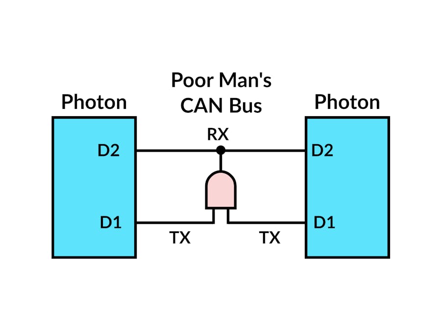
Poor Man's CANSo now we know that to make a simple CAN bus we need 2 devices that support CAN like the Photon, 2 transceivers and 2 wires for the bus itself.
For learning and prototyping there's a simpler alternative.
We can exploit the fact that when all devices on the CAN bus transmit "1" (CAN TX set to HIGH), the bus stays at logical "1" and as soon as one device transmits a "0" (CAN TX set to LOW), the bus goes to logical "0". The device that tries to transmit "0" while another transmits "1" wins the bus so to speak.
This means we can implement a Poor Man's CAN transceiver with an AND gate! Either use a 7408 2-input AND gate, a 7421 4-input AND gate and wire unused inputs to power, or make custom AND gate with transistors you have lying around.
This is of course not for a real project where you'll put the devices away from each other but it will let you tinker and learn about CAN before you invest in real transceivers.
This will also not work to connect a Photon to a real CAN bus like the one in the OBD port of your car. For that you need Carloop (I'm one of the creators).
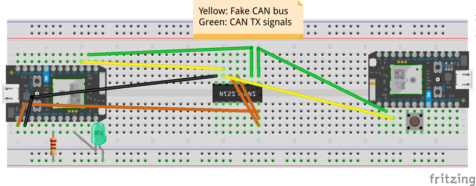
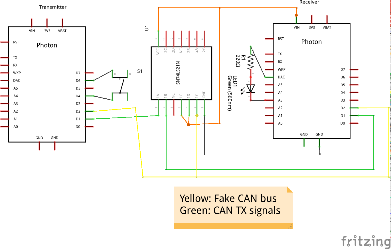
Try it yourselfYou can build the circuit shown in the schematics below. Use any AND gate chip you have available; just be sure to check the pinout. Flash the code for both the Transmitter and Receiver. The Transmitter continuously sends the state of the button in byte 0 of CAN message 0x100 and the Receiver polls for this message. When you press the button on the Transmitter, the LED will turn on in the Receiver.
When you're ready for a project, make sure to get some real transceivers! You can search for "CAN bus transceiver breakout" online and buy some from your favorite reseller.


Comments
Please log in or sign up to comment.