SG Electronic Systems was born as a support to the Open Hardware projects. Our experience allows us to support the Open Hardware team in the development of new electronic systems and in their distribution. We have a long experience in Fieldbus applications as: CAN BUS, RS-232, RS-422/485, Ethernet.
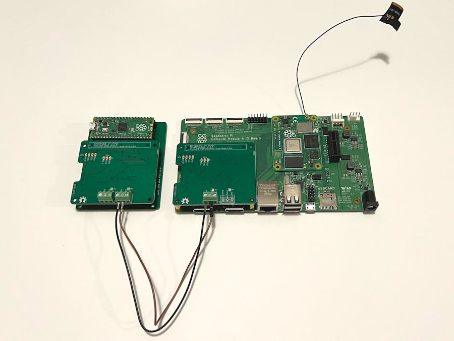
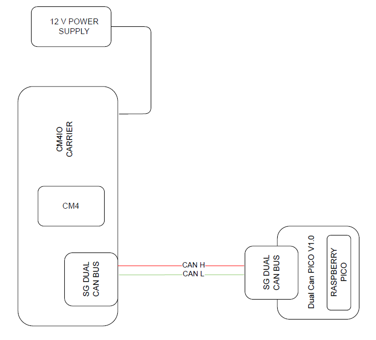
In this tutorial we explain how to program the Raspberry PICO as a double CAN BUS logger. The hardware setup is composed by Master Board (to send CAN BUS data) and Slave Board (for message recording). The Master Board is the official carrier CM4IO with a CM4 module and CAN BUS Shield. The Slave Board is the Raspberry Pico with an adapter for DUAL CAN BUS Shield.
The CM4IO requires a 12 V DC power supply, instead the PICO is powered from USB cable. On can side, the connection requires a a couple of wires for CAN High and CAN Low (CAN High is connected with CAN High, CAN Low is connected with CAN Low).
Software configuration for Raspberry CM4Edit /boot/config.txt modify the following row
dtoverlay=mcp2515-can0, oscillator=16000000, interrupt=22dtoverlay=mcp2515-can1, oscillator=16000000, interrupt=25
Run the following command:
pi@raspberrypi ~ $ dmesg | grep -i can
This is the output:
[ 13.197388] CAN device driver interface[ 15.375846] mcp251x spi0.0 can1: bit-timing not yet defined[ 15.382408] mcp251x spi0.1 can0: bit-timing not yet defined
From the output it is possible to observe that can0 is associated to spi0.1 and can1 to spi0.0.
Respect the board shown in figure 1 the interface can0 is located in SPI0.1(X2 connector) and can1 in SPI0.0(X1 connector).
After your raspberry has been booted, go to home directory:
cd /home/pi/nano can-start.sh
add these lines to the script
#!/bin/sh#Canip link set can0 up type can bitrate 1000000ip link set can1 up type can bitrate 1000000
Run the script:
sudo sh can-start.sh
Software configuration for Raspberry PICOAn embedded system is very interesting for open hardware community only if it is well supported with free IDE and library. There are two IDE software to develop firmware: Arduino IDE and Visual Studio Code.
For stability and simplicity we prefer to use Arduino IDE. The RP2040 core used in this example is developed by Earle Philhower. Use the following steps to prepare the IDE:
- Open IDE
- Click on File
- Click on Preference
Click on Additional Board Manager URLs and add this link https://github.com/earlephilhower/arduino-pico/releases/download/global/package_rp2040_index.json
- Click OK
- Click on Tools
- Click on Board Manager
- Install RP2040 core
- Install ACAN2515 of Pierre Molinaro
- Click on Sketch
- Include Library
- Manage Libraries
- Select Raspberry Pi PICO
On Dual CAN BUS Shield there are two kind of RTC for our boards, the DS3231 and PCF85063. Verify the installed RTC on your board and enabled the correct #define. For this tutorial the RTC #define is not necessary.
Both CAN BUS interface are enabled, CAN0 is set at 125 kb/s instead CAN1 is set at 1 Mb/s.
Copy the compiled file PicoDualCan_V1.0_sniffer.ino.rpipico.uf2 in PICO flash memory.
Logger testOn Raspberry CM4 board run the following command
On Arduino IDE open the PICO serial port
Check if both the CAN interface are initialized without errors, after that you can see message received by PICO.
Remember that, on CM4 can bus can0 was initialized at 1 Mb/s, on PICO can1 is initialized at 1 Mb/s


Comments
Please log in or sign up to comment.