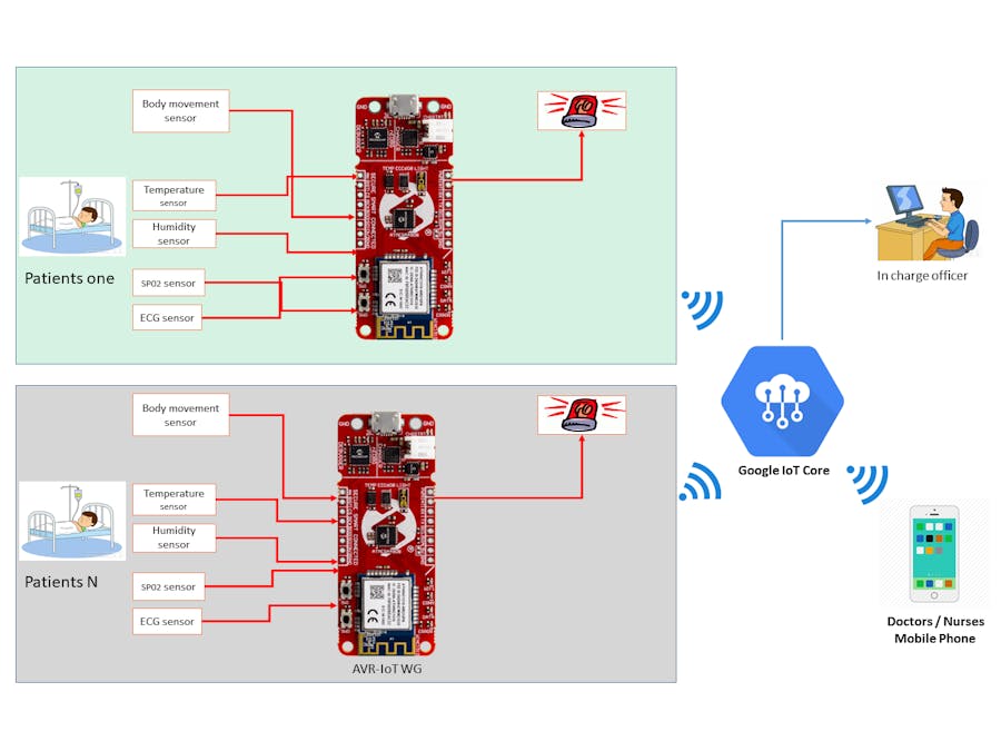
We have proposed an intelligent patient monitoring system to automatically monitor the patients’ health condition through sensors-based connected networks. This system is specially designed for Covid-19 patients. Several sensors are used for gathering the biological behaviors of a patient. The meaningful biological information is then forwarded to the IoT cloud. The system is more intelligent that can detect the critical condition of a patient by processing sensors data and instantly provides push notification to doctors/nurses and hospital in-charge personal. The doctors and nurses get benefited from this system by observing their (corresponding) patients remotely without visiting in person. Patients’ relatives can also get benefited from this system with limited access.
HARDWARE COMPONENT LISTDevelopment Board (AVR-IoT WG)Features:
- ATmega4808 micro-controller
- TEMT6000 Light sensor
- MCP9808 Temperature sensor
- ATECC608A Crypto Authentication™ device
- WINC1510 WiFi Module
- On-board nEDBG Debugger
- USB and battery powered
- Integrated Li-Ion/Lipo battery charger
The Arduino Uno is an open-source microcontroller board based on the Microchip ATmega328P microcontroller and developed by Arduino.cc.[2][3] The board is equipped with sets of digital and analog input/output (I/O) pins that may be interfaced to various expansion boards (shields) and other circuits.[1] The board has 14 digital I/O pins (six capable of PWM output), 6 analog I/O pins, and is programmable with the Arduino IDE (Integrated Development Environment), via a type B USB cable.[4] It can be powered by the USB cable or by an external 9-volt battery, though it accepts voltages between 7 and 20 volts.
This board has an inbuilt temperature sensor and a light sensor that a preloaded firmware publishes the data from the sensors to the cloud (Google Cloud).
The AVR-IoT WG development board features two sensors:
• A light sensor
• A high-accuracy temperature sensor - MCP9808
In addition to this, we plan to use a few more sensors with Arduino Uno that will be explained further.
Step 2: Adding the Device to the CloudFirst, log in to the Google IoT core and create a new project and note your Project ID, which will be needed later when you program the hardware to connect to the project.
Note: Here, I had used a free trial account of the Google Cloud service. In the Google Cloud console, you can find the IoT core at the sidebar.
Create a Registry:
To Register the device:
Note the Device ID from the Click me file, which will direct you to a link.
In the next form, Fill up device ID with an alphabet at first, the Public key format is of ES256 which can be verified, and add the PUBKEY.txt file in the add device page.
After this step, the device is successfully added to the Google Cloud.
Now, Go to the ATMEL START program and enter your Project ID, Registry ID. i.e. Project ID: avr-iot, Registry ID: AVR-IoT and MQTT host: mqtt.googleapis.com in case of our project.
Finally, Export the project to ATMEL Studio 7 and enable the debugger to start the program.
Step 3: Adding Other Sensors Using Arduino UnoConnecting Heart Rate sensor and BME280 sensorThe MAX30100 is an integrated pulse oximetry and heart-rate monitor sensor solution. It combines two LEDs, a photodetector, optimized optics, and low-noise analog signal processing to detect pulse oximetry and heart-rate signals. The MAX30100 operates from 1.8V and 3.3V power supplies and can be powered down through software with negligible standby current, permitting the power supply to remain connected at all times.
Bosch has stepped up their game with their new BME280 sensor, an environmental sensor with temperature, barometric pressure and humidity. This sensor is great for all sorts of indoor environmental sensing and can even be used in both I2C and SPI. This precision sensor from Bosch is the best low-cost sensing solution for measuring humidity with ±3% accuracy, barometric pressure with ±1 hPa absolute accuracy, and temperature with ±1.0°C accuracy. Because pressure changes with altitude, and the pressure measurements are so good, you can also use it as an altimeter with ±1 meter or better accuracy.
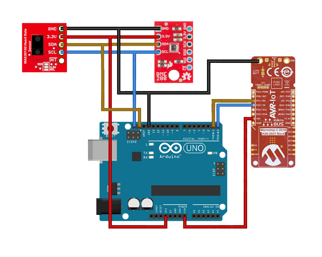
Connections :
Arduino --------------- MAX30100
VCC(3.3v)        ->     VCC(3.3v)
GND              ->     GND(0V)
SCK              ->     SCK
SDA              ->     SDA

Arduino --------------- BME280
VCC(3.3v)        ->     VCC(3.3v)
GND              ->     GND(0V)
SCK              ->     SCK
SDA              ->     SDA

***Please refer the circuit diagram.
We have connected both sensors via I2C bus. By default, both sensors have different bus addresses, which avoids collision.
Step 4: Uploading the FirmwareBefore uploading the firmware, we have to create a bus (UART) to connect Arduino with the Microchip AVR-IOT-WG Board.
UART Connections :
Arduino ------------------ Microchip AVR-IOT-WG Board
VIN                  ->    VCC(5.0 V)
GND                  ->    GND(0 V)
D0 (RX)              ->    PC0 (TX)
D1 (TX)              ->    PC1 (RX)
Once the connection is done upload the code for sensors using Arduino IDE. The code is added to the GitHub Repository, which can be found in the code section.
In case of Microchip AVR-IOT board, export the project from ATMEL START.
Select the solution configuration as release and debugger as UDPI as nEDBG.
Finally, press the green arrow next to Solution configuration to start the program.
Note: Make sure that the program is properly uploaded without errors.
Step 5: Setting Up the Google Cloud for Publish and SubscribeCreate a new function in the Google Cloud Functions.
Set the following parameters:
- Trigger - Cloud Pub/Sub
- Topic - AVR-IOT
It automatically generates the code for PUB/SUB functions.
Step 6: Checking the published data on Google CloudThe data is being published on the Google Cloud. This data, which is logged, can be displayed on either a website or a mobile application.
We have developed a mobile application for monitoring the patient remotely. The mobile application shows the biological information of the patient. Those information are heart rate, spo2, body temperature, and humidity, etc.
** The Demo APK is added to the GitHub Repository, which can be found in the code section. Login information is available in the login.txt file.
The Proposed Device (prototype)All personal identifying information and medical health data are encrypted. Only authorized persons have access to the data.
ConclusionOur proposed system, described in this project, allows doctors or nurses, and hospital in-charge personal allows them to monitor the patient in the ICU unit in real-time, improving efficiency and service quality. There is a huge opportunity to modify this system as a wearable device that monitors older people or babies remotely from anywhere.
Reference1. "Arduino UNO for beginners - Projects, Programming and Parts".makerspaces.com. Retrieved 20 January 2021.
2. http://medea.mah.se/2013/04/arduino-faq/
3. "What is Arduino?".learn.sparkfun.com. Retrieved 20 January 2021.
4. "Introduction to Arduino" (PDF). priceton.edu. Archived from the original (PDF) on 3 April 2018. Retrieved 20 January 2021.
5. Uddin, M. S., Alam, J. B., & Banu, S. (2017, September). Real time patient monitoring system based on internet of things. In 2017 4th International Conference on Advances in Electrical Engineering (ICAEE) (pp. 516-521). IEEE. DOI: 10.1109/ICAEE.2017.8255410
6. Adafruit BME280 I2C or SPI Temperature Humidity Pressure Sensor, https://www.adafruit.com/product/2652
7. MAX30100; Pulse Oximeter and Heart-Rate Sensor IC for Wearable Health, https://www.maximintegrated.com/en/products/sensors/MAX30100.html


_ztBMuBhMHo.jpg?auto=compress%2Cformat&w=48&h=48&fit=fill&bg=ffffff)


_1x_bGT19vVAby.png?auto=compress%2Cformat&w=40&h=40&fit=fillmax&bg=fff&dpr=2)

_3u05Tpwasz.png?auto=compress%2Cformat&w=40&h=40&fit=fillmax&bg=fff&dpr=2)
Comments
Please log in or sign up to comment.