Principle
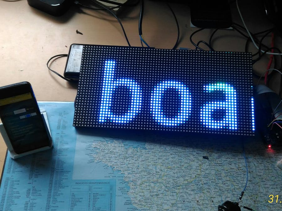
A Family Board is a led matrix that displays a message sent by a mobile phone ; members of the family may acknowledge the message using an arcade button connected to the Family Board ; when the button is pressed a notification is sent to the mobile phones that have the application. What's more a sonar detects when someone is in front of the led matrix and send a notification to the mobile phones. Messages, button action and sonar detection are usins AWS IOT publish and AWS SNS push notifications.
Video of the Family Board created
Hardware parts for the project
Hardware
- Iphone
- Raspberry Pi Model B+
- RGB Hat
- Led matrix :
- Arcade Button :
- Alimentation Mean-Wheel
- Ultrasonic Sensor HC-SR04
Software
- XCode 7 (code in Swift 2) for iPhone mobile application
- Python IDE
- MQQT.fx : http://mqttfx.jfx4ee.org/index.php/download
- Bitwise SSH Client (SSH and SFTP to transfer files and connect to Raspberry Pi)
How Family Board Works
Assembly of RGB Hat that will drive the led matrix
You will find all necessary information on Adafruit tutorial : https://learn.adafruit.com/adafruit-rgb-matrix-plus-real-time-clock-hat-for-raspberry-pi/assembly
You will need to solder some parts, on Adafruit Website these steps are very well described and documented.
Plug the RGB Hat to the Raspberry Pi
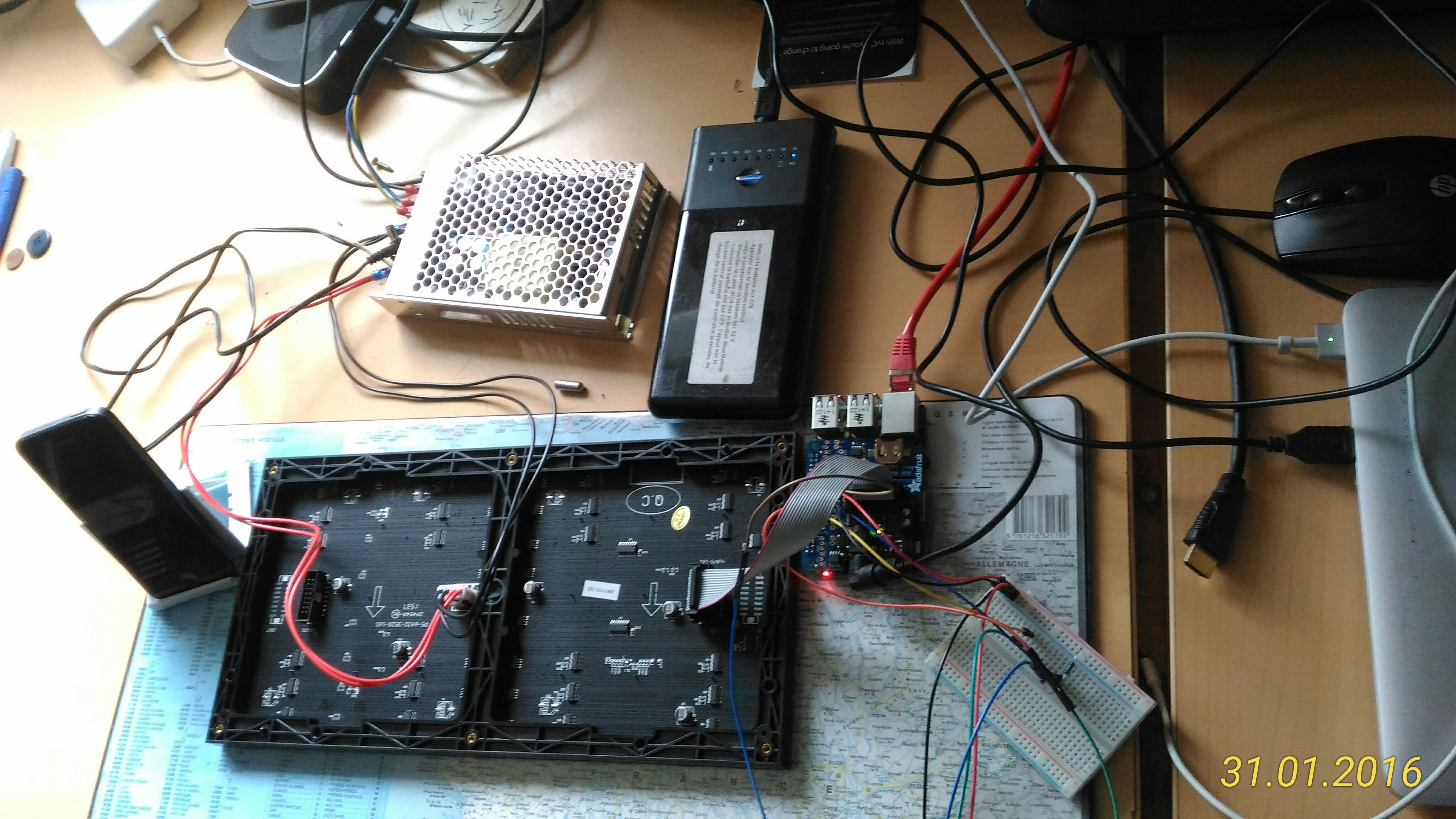
Connect the Led Matrix to the RGB Matrix
Compare to Adafruit tutorial, I have made some changes because I had some alimentation problems, the Led matrix was glitching and it had poor result (may be it is a problem with soldering of RGD Hat ...) ; so I have two different alimentation : the Mean Well (5V - 22 A) for the Led Matrix and a 5V battery connected to the jack of RGB hat.
Download software to raspberry Pi and test it
Using Bitwise SSH Client and Bitwise SFTP you may connect to the matrix and test RGB Hat and Led Matrix
To install and test led matrix, follow steps : https://learn.adafruit.com/adafruit-rgb-matrix-plus-real-time-clock-hat-for-raspberry-pi/driving-matrices
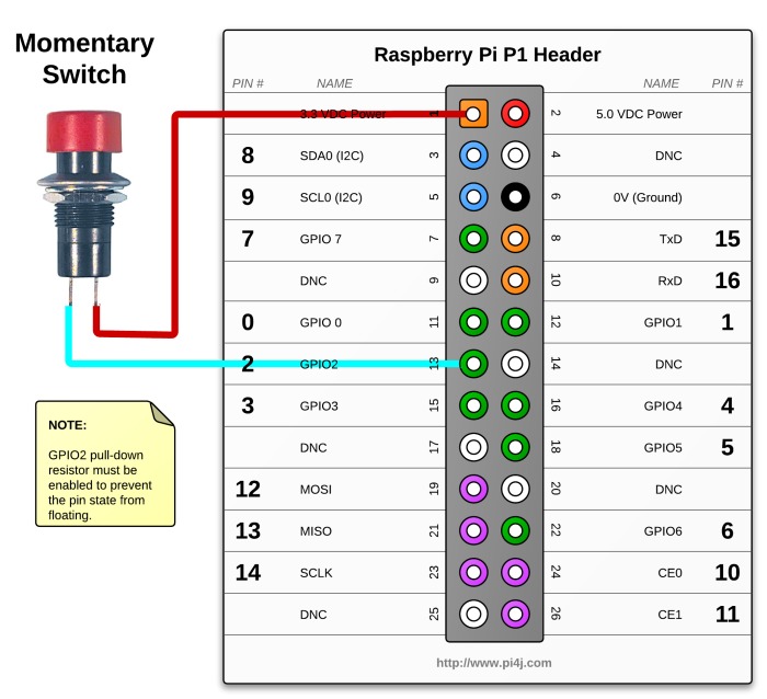
Solder the button to RGB Hat
With RGB hat on Raspberry Pi, you don't have directly access to GPIO and many of GPIO are used by RGB Hat but on RGB Hat you may still have access to some free GPIOs ; I have chosen GPIO 18 for arcade button and GPIO 24 and 25 for Ultrasonic sensor
You also may fin a tutorial here : https://www.cl.cam.ac.uk/projects/raspberrypi/tutorials/robot/buttons_and_switches/
Below is the code to test the button :
#!/usr/bin/env python2.7
import RPi.GPIO as GPIO
GPIO.setmode(GPIO.BCM)
# Le GPIO 18 est initialise en entree. Il est en pull-up pour eviter les faux signaux
GPIO.setup(18, GPIO.IN, pull_up_down=GPIO.PUD_UP)
print "Veuillez verifier que vous avez un bouton connecte de telle maniere"
print "qu il connecte le port GPIO 23 (pin 16) au GND (pin 6)\n"
raw_input("Pressez Entree quand vous etes pret\n>")
print "En attente de signal sur le port GPIO 18"
# a partir de la, le script ne fera plus rien jusqu a ce que
# le signal sur le port 18 commence a chuter vers zero. C est
# la raison pour laquelle nous avons utilise le pull-up pour
# garder le signal "HIGH" et empecher un faux signal
print "Pendant ce temps votre Rapsberry Pi ne gaspille pas"
print "de ressources en attendant un appui sur le bouton.\n"
print "Pressez le bouton quand vous voulez lancer un signal."
try:
    GPIO.wait_for_edge(18, GPIO.FALLING)
    print "\nAppui detecte. Maintenant votre script va"
    print "effectuer l'action correspondant a un appui sur le bouton."
except KeyboardInterrupt:
    GPIO.cleanup()       # reinitialisation GPIO lors d'une sortie CTRL+C
GPIO.cleanup()           # reinitialisation GPIO lors d'une sortie normale
Copy the code to the raspberry and test it. Don't forget to use sudo because root level is required when using GPIOs
sudo python <code.py>
Connect the Ultrasonic Sensor
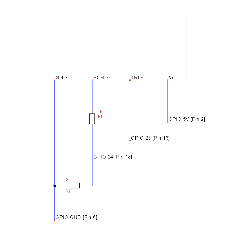
I have not solder the HC-SR04 Ultrasonic sensor on the RGB Hat, I have use a breadboard and some resistance
You will find a tutorial here : http://www.modmypi.com/blog/hc-sr04-ultrasonic-range-sensor-on-the-raspberry-pi
GPIOs used are 24 and 25.
Code :
import RPi.GPIO as GPIO
import time
GPIO.setmode(GPIO.BCM)
TRIG = 24
ECHO = 25
print "Distance Measurement In Progress"
GPIO.setup(TRIG,GPIO.OUT)
GPIO.setup(ECHO,GPIO.IN)
GPIO.output(TRIG, False)
print "Waiting For Sensor To Settle"
time.sleep(2)
GPIO.output(TRIG, True)
time.sleep(0.00001)
GPIO.output(TRIG, False)
while GPIO.input(ECHO)==0:
  pulse_start = time.time()
while GPIO.input(ECHO)==1:
  pulse_end = time.time()
pulse_duration = pulse_end - pulse_start
distance = pulse_duration * 17150
distance = round(distance, 2)
print "Distance:",distance,"cm"
GPIO.cleanup()
<br/>
All hardware is now on place.
Now we can configure AWS services (IOT and SNS for push notifications)
AWS configuration
I recommend the Amazon documentation for AWS IOT : http://docs.aws.amazon.com/fr_fr/iot/latest/developerguide/iot-quickstart.html
There are 2 different ways to use IOT : with console (AWS CLI) or with interface.
I recommend you to use AWS interface with all steps described in AWS CLI :
You will need to create 3resources are mandatory : a thing, a certificate and a policy
Creation of the thing :
Connect a device with certificate creation
Get the certificates
First, you will need to create and download security credentials for your device. The following steps will help you to create and download security credentials (a certificate for authentication, and a policy that defines what the device using this certificate is allowed to do).
You can generate a certificate with 1-click. When you generate a certificate, we will also generate a default security policy named ThingAWSTest03-Policy. You can modify this security policy at any time through the 'Resources' panel of this console.
Get the ids and the code
To get the root CA, connect to the Raspverry Pi and write the command :
mkdir /root/keywget -O /root/key/root-CA.crt “https://www.symantec.com/content/en/us/enterprise/verisign/roots/VeriSign-Class 3-Public-Primary-Certification-Authority-G5.pem”
You may test the communication using MQTT.fx : https://docs.aws.amazon.com/fr_fr/iot/latest/developerguide/verify-pub-sub.html
Configure AWS SNS for Push notifications :
I recommend you to read the tutorial ; follow each step carefully, the first time you do it, it is quite difficult but push notifications are so powerful and required in each mobile application now ...
AWS SNS : http://docs.aws.amazon.com/fr_fr/sns/latest/dg/mobile-push-apns.html
Create rules to send push notification send arcade button is pressed or sonar detects someone in front of the led matrix
Once you have created your push SNS topic, it is very easy to create a rule that will send a message to the topic when a message is publish on an iot topic; that's very powerful and very well integrated in AWS, it is automatic ...
iPhone mobile application
The mobile application is code using XCode 7 and Swift 2.
The mobile phone subscribe to SNS topic to receive notifications when button is pressed or when sonar detects presence.
The mobile send messages to the display using AWS IOT publish.
Screenshots of the application
The application was created using example codes from Amazon : https://github.com/awslabs/aws-sdk-ios-samples


Comments
Please log in or sign up to comment.