Project Description
This Make It Matter Challenge project converts a traditional standing desk into an IoT device using the Matter protocol. The aim is to enhance the functionality and user experience of a standing desk by incorporating IoT capabilities, allowing it to become part of the interconnected smart home ecosystem and seamlessly communicate with other Matter-enabled devices. Our app is easy to install, and acts as the matter controller allowing for remote operation of the standing desk.
The intended audience for this project is mainly for persons spending more than 4 hours of sedentary time at a desk. The project could also come in use for users with disabilities, since voice control can easily be adapted for this project.
With the ability to connect the standing desk to a smart home ecosystem, the user has the ability to enhance it's functionality of the desk. Often times when using standing desks, the user can disregard the controls for height adjustment, rendering the standing desk useless.
Transforming a standing desk into an Internet of Things (IoT) device can allow the user to setup routines on their smart home ecosystem, allowing them to routinely change the height of the desk at different periods of the day.
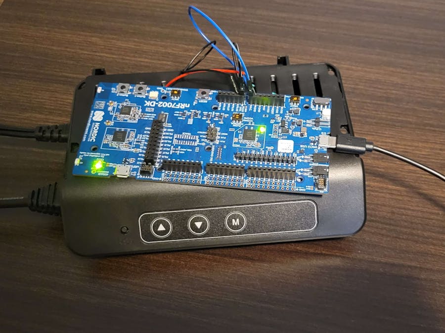
Note: We understand that control displays for standing desks vary depending on the model and manufacturer. We've accommodated this by connecting the transistors directly to the control display's up and down buttons. Note: We’ve not included the instructions for setting up the standing desk since this may vary from model and manufacturer.
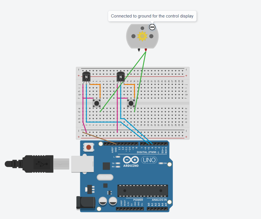
- Open standing desk control panel and locate the up and down buttons
- Solder the emitter and collector of the generic transistor (We use PN2222) to the up and down buttons
- The emitter is the green and red wire, the collector is the yellow and black wire
- Next, connect the emitter to the ground pin of the nrf7002 board (i.e. The emitter should have two wires soldered to it)
Note: Take extra precaution when making these connections. One side of the button is connected to power, while the other side is connected to ground. If the side connected to power for the button is grounded, the motor will become active without the user's intent.
- Finally, connect the base of the generic transistor to the pins allocated for up and down buttons. We’ve used pin 4 (UP) and pin 5 (DOWN) in our example code
By the end, the final hardware configuration should look like this:
You may connect the motor and the power cable for the control display to start testing the connections
SoftwareNote: We understand that the functionality for the control displays for standing desks vary depending on the model and manufacturer. You may simply accommodate for this by changing the duration of time the GPIO pin for the up and down buttons are left on.
- Download the nRF Connect SDKDownloading the nRF Connect SDK to the development process for the nRF7002 board.You may find a link to the nRF Connect SDK here: https://www.nordicsemi.com/Products/Development-software/nrf-connect-sdkThe following SDK was used in our project:
- Download the Visual Studio Code - nRF Connect ExtensionWhile not mandatory, we found it simple to use the nRF Connect Extension with VS code to browse samples, create the build configurations, and flash the board with the compiled code.You may find a link to the nRF Connect Extension here: https://marketplace.visualstudio.com/items?itemName=nordic-semiconductor.nrf-connect
- Clone the Github Repo - Embedded code (matter)The following is a portion of the following repository: https://github.com/AkifManzoor124/standing-desk-make-it-matter
- Google Sample app
The link and tutorial for running the sample app can be found here: https://developers.home.google.com/samples/matter-app?authuser=0And here: https://github.com/google-home/sample-apps-for-matter-android/releases/tag/v1.4.1We simply downloaded the apk for the GHSAFM app, and were able to have the app running as soon as it finished downloading. Here is what the app should look like:
Keep in mind that you won’t see LIGHT BULB SAMPLE until the device is connected to the board.
- Creating the Build Configuration
You may use the following configurations to build the code for your nRF7002 development kit.
Once built, you may press the flash button to flash the nRF7002 board.
- Expected behavior of the boardThe github repo was created on top of the sample bulb sample provided by Nordic Semiconductors You may learn more about the behavior of the board after flashing here: https://developer.nordicsemi.com/nRF_Connect_SDK/doc/2.2.0/nrf/samples/matter/light_bulb/README.html
- Connecting the App to the boardPress on the big + button on the app, and start the process for connecting your nRF7002 board to the appYou will be prompted to scan a QR code which can be found here for the light bulb sample code: https://project-chip.github.io/connectedhomeip/qrcode.html?data=MT%3A6FCJ142C00KA0648G00You may encounter the following screens:
- If you’ve input the name of the device as STANDING DESK, you will see the following screen:
- Testing the behavior of the board while connected to the app
- NOTE:
You may use double sided tape to install the nRF board to the bottom of the control panel. - Depending on your standing desk model, you can install the control display to the bottom of the table top to improve the aesthetics of the project.
- We did not include instructions for connecting the nRF board to a smart home ecosystem due to the variety of availably options in the market.
OUR MOTIVATION


Comments
Please log in or sign up to comment.