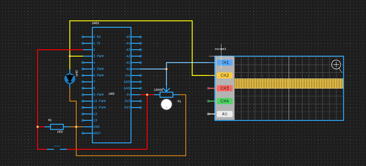
This project demonstrates the use of an Arduino UNO, a potentiometer, a push button, and an oscilloscope to control the brightness and blinking pattern of an LED.
Circuit SimulationOnline Simulation here.
DescriptionThe Arduino code initializes the pin modes and continuously reads the potentiometer's value to adjust the LED's brightness. It also checks the push button's state to toggle between two blinking modes. The analogWrite() function is used to set the LED's brightness.
The potentiometer's middle terminal voltage can be observed on an oscilloscope, showing a linear change as the knob is turned.
The push button's signal can be monitored to see the transition between LOW and HIGH states when pressed and released.
PCBX Simulation UpdateMore technical, suitable for a product roadmap or feature list:
- New components: potentiometer, shift register, push button switch;
- New instruments: oscilloscope function, circuit calculation optimization, UI optimization (resizable sidebar, collapsible IDE sidebar).
Get your first free PCB & PCBA prototyping here


_ztBMuBhMHo.jpg?auto=compress%2Cformat&w=48&h=48&fit=fill&bg=ffffff)


Comments