Hackster is hosting Hackster Holidays, Ep. 7: Livestream & Giveaway Drawing. Watch previous episodes or stream live on Friday!Stream Hackster Holidays, Ep. 7 on Friday!
Srinjit Bhattacharyya
Published

IOT based Thermal Alarm

An IoT based thermal alarm system that goes off and sends SMS when it detects a thermal anomaly.

IntermediateFull instructions provided277
IOT based Thermal Alarm

Things used in this project

Hardware components

Bolt WiFi Module
Bolt IoT Bolt WiFi Module
×1
Buzzer, Piezo
Buzzer, Piezo
×1
5 mm LED: Red
5 mm LED: Red
×1
LED, Blue
LED, Blue
×1
Temperature Sensor
Temperature Sensor
(LM35)
×1

Software apps and online services

SMS Messaging API
Twilio SMS Messaging API

Hand tools and fabrication machines

Premium Female/Male Extension Jumper Wires, 40 x 6" (150mm)
Breadboard, 170 Pin
Breadboard, 170 Pin

Story

Read more

Schematics

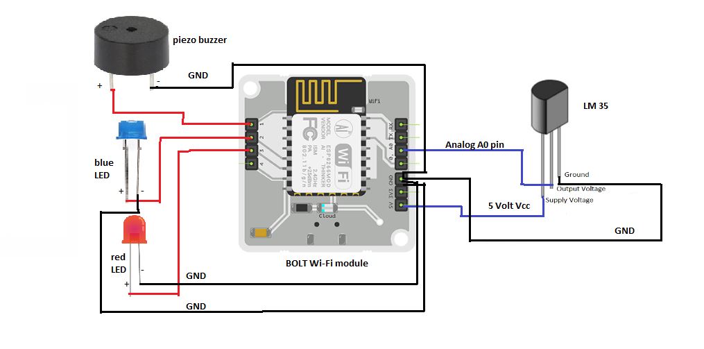
Schematic diagram to implement the circuit

STEP 1 : The ‘+’ marked pin of the buzzer is the positive pin. It is connected to the GPIO 1 port of the Bolt Wi-Fi module.
STEP 2 : The longer legs of the blue and red LEDs are the positive pins. They are connected to the GPIO ports 2 and 3, respectively.
STEP 3 : The ‘-‘ marked pin of the buzzer and the shorter legs of both the LEDs, are the negative pins. All of them are connected to the GND (Ground) port of the Bolt Wi-Fi module.
STEP 4 : The pin configuration of the LM35 sensor is as follows :-
Pin number 1 is connected to the 5V port of Bolt module. Pin number 2 is connected to the Analog A0 pin of Bolt module and Pin number 3 is connected to the GND (Ground) port of Bolt module.

(NOTE : Using a breadboard to do the connections, is preferable as it prevents the over-crowding of wires in the Bolt module.)

Code

Code to implement the project

CODE EXPLANATION Create a separate Python file to store all relevant information pertaining to the Bolt module and Twilio accounts. That file has been named device_info.py Import that file to the main Python file in order to access its contents. Import Bolt and Sms libraries from the boltiot python module. ‘mybolt’ is an object to communicate with the hardware devices. ‘sms’ is an object to communicate with the Twilio servers. Set threshold values for maximum and minimum temperature limits. The online/offline status of the Bolt module is checked via the isOnline() function of the Bolt file. The reading of sensor data proceeds only when the module is online. The sensor data is collected from the A0 pin of the module via the analogRead() function. It is in JSON format hence, we need the JSON python library to parse the received information. The data is further, converted to integer type so that comparisons can be made. The data collected from sensor is the voltage reading. It is converted to corresponding temperature value by dividing the voltage value by 10.24. We employ an infinite loop to continuously check the sensor reading after every 10 seconds. This time interval is set by the ‘time.sleep(10)’ provided at the end of the loop. If the temperature value is greater than the maximum temperature value, a request is issued to the Twilio server to send an alarm SMS to the user’s phone number. Simultaneously, the buzzer makes a shrill sound and the LED at port 2 of the bolt module, starts blinking. If the temperature value is lesser than the minimum temperature value, a request is issued to the Twilio server to send an alarm SMS to the user’s phone number. Simultaneously, the buzzer makes a flat sound and the LED at port 3 of the bolt module, starts blinking. If the temperature is within range then no SMS is sent and digital LOW signals are supplied to the buzzer and both the LEDs. (NOTE : Make sure to upgrade your Bolt cloud to the pro version else your API will be time-rated for 6 hours. The default free version provides only 20 server hits per minute whereas, the programming for this project, goes beyond that.)

Credits

Srinjit Bhattacharyya
1 project • 0 followers
IoT buff with a profound love for programming.

Comments