

Hardware components | ||||||
 |
| × | 1 | |||
 |
| × | 1 | |||
 |
| × | 1 | |||
 |
| × | 1 | |||
 |
| × | 2 | |||
 |
| × | 2 | |||
 |
| × | 1 | |||
 |
| × | 2 | |||
 |
| × | 1 | |||
 |
| × | 1 | |||
 |
| × | 1 | |||
 |
| × | 1 | |||
Hand tools and fabrication machines | ||||||
 |
| |||||
 |
| |||||
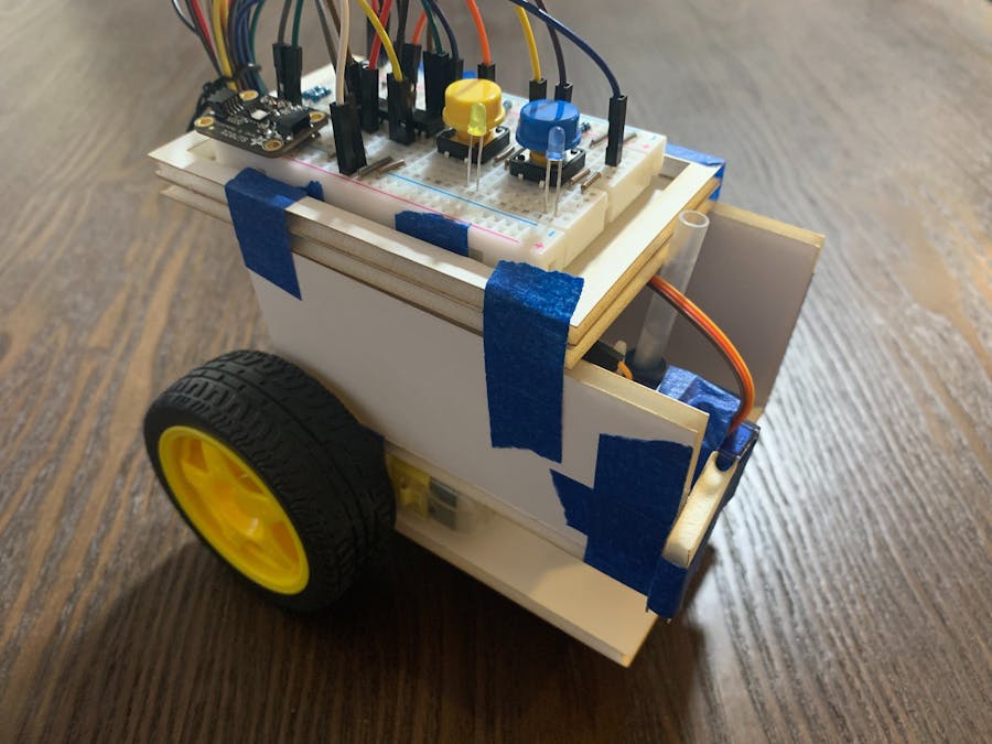
My project is a mood-drawing robot. The project was inspired by the idea of mood rings, which are fun accessories that change color based on the temperature around them. My robot contains a temperature sensor that is able to use body heat to distinguish between times when the user is not covering the sensor and times when the user is covering the sensor. The robot then decides either that it is that it is happy (the user was covering the sensor) or sad (the user was not covering the sensor). Finally, using wheels connected to the chassis and a pen connected to a servo, the robot moves around and draws the user a corresponding smiley or frowny face on a standard sheet of letter paper.
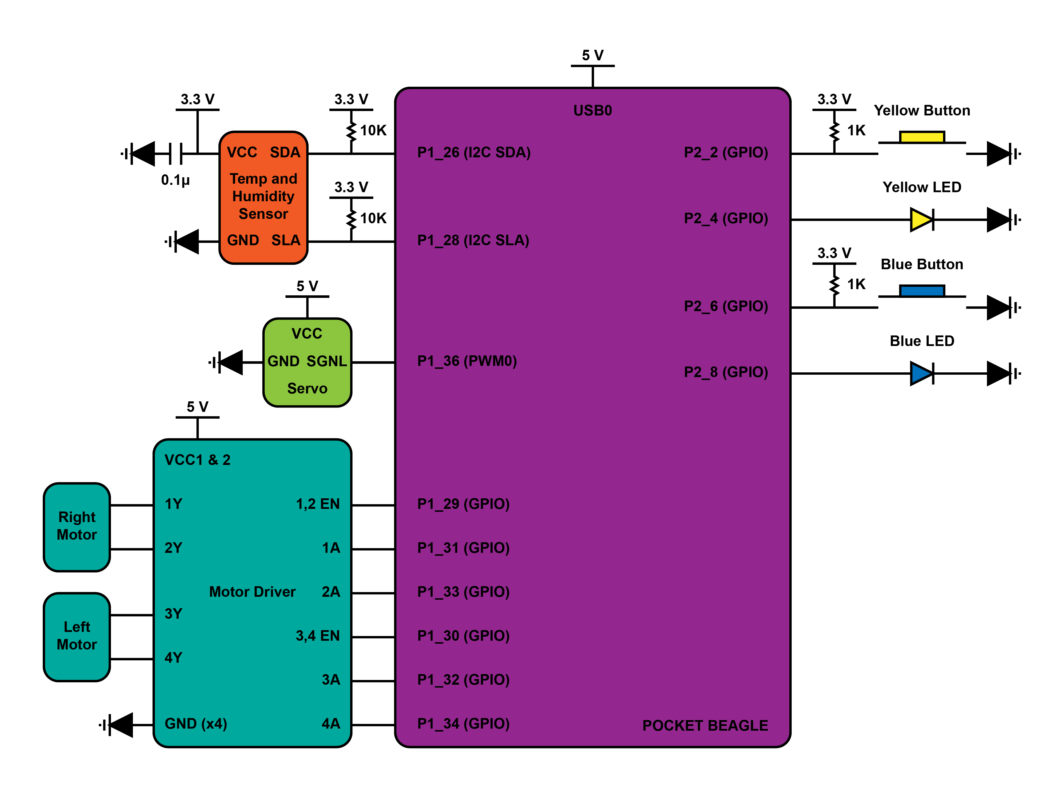
BUILD DIAGRAMSPower Rail 1
- Connect power rail 1 to PocketBeagle P1_14 (3.3 V).
Ground Rail 1
- Connect ground rail 1 to PocketBeagle P1_16 (GND).
Yellow Button
- Connect one pin both to PocketBeagle P2_2 (GPIO) and to a 1KΩ pullup resistor (that is connected to power rail 1).
- Connect other pin to ground rail 1.
Yellow LED
- Connect anode to PocketBeagle P2_4 (GPIO).
- Connect cathode to ground rail 1.
Temperature Sensor
- Connect VIN pin both to a 0.1μF Capacitor (that is connected to ground) and to power rail 1.Connect GND pin to ground rail 1.
- Connect SCL pin both to PocketBeagle P1_28 (SCL) and to a 10KΩ pullup resistor (that is connected to power rail 1).
- Connect SDA pin both to PocketBeagle P1_26 (SCL) and to a 10KΩ pullup resistor (that is connected to power rail 1).
Blue Button
- Connect one pin both to PocketBeagle P2_6 (GPIO) and to a 1KΩ pullup resistor (that is connected to power rail 1).
- Connect other pin to ground rail 1.
Blue LED
- Connect anode to PocketBeagle P2_8 (GPIO).
- Connect cathode to ground rail 1.
Servo
- Connect VCC pin to PocketBeagle P1_24 (5V VOUT).
- Connect GND pin to PocketBeagle P1_22 (GND).
- Connect SIGNAL pin to PocketBeagle P1_36 (PWM0).
Power Rail 2
- Connect power rail 2 to PocketBeagle P1_7 (5V VIN).
Ground Rail 2
- Connect ground rail 2 to PocketBeagle P1_15 (GND).
Motor Driver and Left/Right Motor
- Connect VCC2 and VCC1 pins to power rail 2.
- Connect four GND pins to ground rail 2.
- Connect 1, 2EN pin to PocketBeagle P1_33 (GPIO).
- Connect 1A pin to PocketBeagle P1_31 (GPIO).
- Connect 1Y pin to right motor red wire.
- Connect 2Y pin to right motor black wire.
- Connect 2A pin to PocketBeagle P1_29 (GPIO).
- Connect 3, 4EN pin to PocketBeagle P1_30 (GPIO).
- Connect 3A pin to PocketBeagle P1_32 (GPIO).
- Connect 3Y pin to left black motor wire.
- Connect 4Y pin to left motor red wire.
- Connect 4A pin to PocketBeagle P1_34 (GPIO).
Chassis
- Laser cut chassis vector template out of foam core.
- Using hot glue, assemble foam chassis so that
- (first) the wheels and back wooden dowel are between levels 1 and 2.
- (second) the PocketBeagle and servo are between levels 2 and 3.
- (third) the solderless breadboard is above level 3.
- (fourth) the front wooden dowel and pen go from the ground to above level 2.
- Tie the servo to the pen with a thin wire; ensure servo pushes pen down into the ground when ‘on’ and pulls pen up off the ground when ‘off’.
There are four main documents in the repository linked at the end of this project.
1. The main script titled robot.py contains all library imports, constants, global variables, function and class definitions, and main name call code.
2. The pin configurations titled configure_pins.sh configures specific pins for I2C and GPIO as needed.
3. The run script titled run runs configure_pins.sh then robot.py.
4. The ReadMe provides the build and operation instructions.
OPERATION INSTRUCTIONS1. Run the command ./run in the command line to run the run script.
- The pins should be configured.
- The program should initialize.
- The program should print "Program Start".
2. Press the yellow button while either covering or not covering the temperature sensor.
- The yellow LED should turn on.
- The temperature should be recorded and the mood (happy or sad) decided.
- The yellow LED should turn off.
2. Set the robot on a standard sheet of letter paper so that
- (first) the paper is in a vertical orientation.
- (second) the wooden dowel is on the top left corner of the paper.
- (third) the front of the robot is facing and parallel to the top edge of the paper.
3. Press the blue button.
- The blue light should turn on.
- The robot should drive around while picking up and putting down the pen.
- The robot should draw a smiley or frowny face.
- The blue light should turn off.
4. The ‘temperature’ function and ‘drawing’ function do not have to be linear. This means the temperature can be re-recorded by hitting the yellow button directly after the previous temperature sequence. And the robot can re-draw the same smiley or frowny face by hitting the blue button directly after the previous drawing sequence.
AUTOBOOT ON POWER UPTo make the run script automatically run on power up, enter the cron scheduler of the PocketBeagle by running the command sudo crontab -e on the command line and entering the correct username and password when prompted.
sudo crontab -eIn the crontab window, enter the line below to cause the PocketBeagle after reboot to sleep for 30 seconds, run the run script, and save all outputs to logs. Exit the crontab and save the edits.
@reboot sleep 30 && sh /var/lib/cloud9/ENGI301/project_01/run > /var/lib/cloud9/logs/cronlog 2>&1Ensure that the directory /var/lib/cloud9/logs exists. This is where outputs from the run script including error messages are recorded. If it does not exist, create a new directory by running the command mkdir logs on the command line.
mkdir logsTurn the PocketBeagle off and back on, and the run script should run automatically.
DEMO VIDEOIn this project, the temperature sensor did not do a great job overall of recording body heat as a substantial change from the room temperature. As such, the code had to be set based on the temperature of the room so that when the body heat raised the temperature by 0.1-0.3 C, it would register as a change from 'sad' to 'happy'. Next steps would include finding and using a sensor that measures temperature much more locally and reads human body temperature at its true skin temperature of 33 C.
Additionally, the path which the robot follows to create a drawing is not very repeatable. Starting from the same position on the same piece of paper on the same table often generated varying placements of the drawing and varying spacing between parts of the drawing. Furthermore, if the paper was placed in a different spot on the same not-perfectly flat table or on another table altogether, the drawing become so distorted as to often miss the piece of paper completely. Next steps would include finding a way to fine tune the output of the DC motors so that the drawing is consistent every time.


Comments