


Hardware components | ||||||
 |
| × | 1 | |||
Hand tools and fabrication machines | ||||||
 |
| |||||
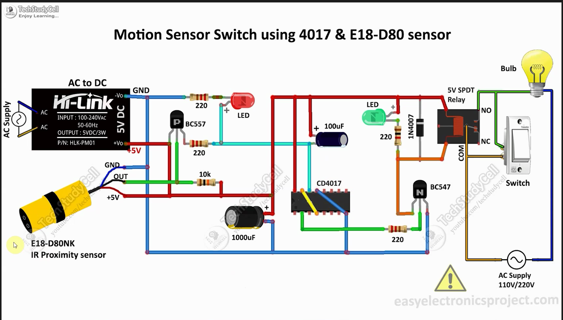
In this CD4017 project, I have shown how to make a simple motion sensor switch using 4017 IC and E18-D80NK IR proximity sensor to automate the washroom light.
You can also use this circuit as a motion sensor alarm.
When anyone enters the toilet the IR proximity sensor senses the motion and turns on the light, and when he or she exits from the washroom the IR sensor again senses the motion and turns off the light automatically.
The range of the E18-D80NK IR sensor is very good and the range also can be adjusted. So the sensor can easily detect motion to control the toilet light automatically. You can also adjust the range of this sensor.
You can also control the light manually using the switch as shown in the picture,
You can also make the complete circuit on a breadboard. You can also download the Gerber file and order the PCB.
Tutorial Video on Motion Sensor Switch using CD4017During the CD4017 project tutorial video, I covered the following topics:
- Explained circuit diagram of the motion sensor switch.
- Test the motion control switch circuit.
- How to connect the motion sensor with AC appliances.
- CD4017 IC
- BC557 PNP Transistor
- BC547 NPN Transistor
- 100uF 25V Capacitor
- 1000uF 25V Capacitor
- 220-ohm 0.25watt Resistors - 3 no
- 1k 0.25watt Resistor
- 10k 0.25watt Resistor
- LEDs 5mm - 2no
- E18-D80NK IR proximity sensor
- 1N4007 Diode
- 5V SPDT Relay
- HLK-PM01 5V AC to DC converter
- Connectors & IC Base
- Latched Switches - 2 no
In the circuit, I have used CD4017 and E18-D80NK IR proximity sensor.
How the Motion Sensor Circuit Operates
- The IR proximity sensor consistently emits infrared radiation. When an object enters its range, a portion of the infrared radiation reflects off the object's surface, and this reflected infrared is then detected by the IR proximity sensor.
- Upon detecting motion, the output pin (linked to the base of the BC557 PNP transistor) of the IR proximity sensor shifts to a LOW state, causing the BC557 PNP transistor to activate.
- The clock pin (Pin-14) of the CD4017 IC is linked to the emitter of the BC557 transistor. Consequently, when motion is detected, the CD4017 IC receives a clock pulse, leading to a change in the current state of Pin-2.
- Pin-2 of the CD4017 is connected to the base of the BC547 NPN transistor. As Pin-2 transitions to a high state, the transistor switches on.
- Upon transistor activation, current flows through the relay coil, activating the load connected to the relay.
- When the IR LEDs detect motion for a second time, they generate the next clock pulse for the CD4017 IC. Subsequently, Pin-2 returns to a low state.
- If Pin-2 transitions to a low state, the transistor deactivates, causing the load connected to the relay to turn off correspondingly.
For testing the circuit, I made the circuit on the breadboard. Here I have used 5V DC supply.
While testing the circuit, whenever the IR Proximity sensor detects any object nearby, the Green LED turns ON, and toggles the current state of the relay. The RED LED is the indicator for the relay.
Design the PCB for This Electronics ProjectTo make the circuit compact and give it a professional look, I designed the PCB after testing.
You can download the PCB Gerber file of this project from the following link:
Download PCB Gerber: Download Link
Why you should use JLC SMT Service?On JLCPCB's one-stop online platform, customers enjoy low-cost & high-quality & fast SMT service at an $8.00 setup fee($0.0017 per joint).
$27 New User coupon & $24 SMT coupons every month.
Visit https://jlcpcb.com
JLCPCB SMT Parts Library 200k+ in-stock components (689 Basic components and 200k+ Extended components)
Parts Pre-Order service https://support.jlcpcb.com/article/164-what-is-jlcpcb-parts-pre-order-service
Build a Personal library Inventory, save parts for now or the future
Assembly will support 10M+ parts from Digikey, mouser.
Steps to Order the PCB Assembly from JLCPCB1. Visit https://jlcpcb.com and Sign in / Sign up.
2. Click on the QUOTE NOW button.
3. Click on the "Add your Gerber file" button. Then browse and select the Gerber file you have downloaded.
4. Set the required parameters like Quantity, PCB masking color, etc.
5. Select the Assemble side and SMT Quantity.
6. Now upload the BOM and PickAndPlace files.
7. Now confirm all the components which you want to be soldered by SMT services.
8. Click on SAVE TO CART button.
Select Shipping Address and Payment Mode6. Type the Shipping Address.
7. Select the Shipping Method suitable for you.
8. Submit the order and proceed with the payment.
You can also track your order from the JLCPCB
My PCBs took 3 days to get manufactured and arrived within a week using the DHL delivery option.
PCBs were well-packed and the quality was really good at this affordable price.
Solder All the Components on PCBAfter that, I soldered all the components as per the circuit diagram.
Then connect the CD4017 board with the PCB.
Now connect the 220V AC supply.
Fit the PCB inside the BoxNow, create openings in the plastic enclosure for the LEDs and switch. Afterward, carefully position the PCB inside the box.
Mount the Plastic Enclosure on the WallThen drill holes in the wall to mount the plastic enclosure.
Then place the sensor and PCB as per the circuit.
Connection Diagram for the PCBPlease refer to this connection diagram to connect the sensor, switch and AC supply with the PCB.
A latched switch is connected across the relay to control the light manually.
Another switch is there to connect the 220V supply to the PCB.
Please take proper safety precautions while working with high voltage.
Finally, Our Motion Sensor Switch Is ReadyOur motion sensor switch is ready.
Now when anyone enters the toilet the IR proximity sensor senses the motion and turns on the light, and when he or she exits from the washroom the IR sensor again senses the motion and turns off the light automatically.
I hope you have liked this IR Motion Sensor Switch project. I have shared all the required information for this project.
I would appreciate it if you share your valuable feedback. Also if you have any queries please write in the comment section.
Thank you & Happy Learning.


Comments
Please log in or sign up to comment.