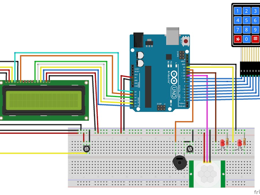
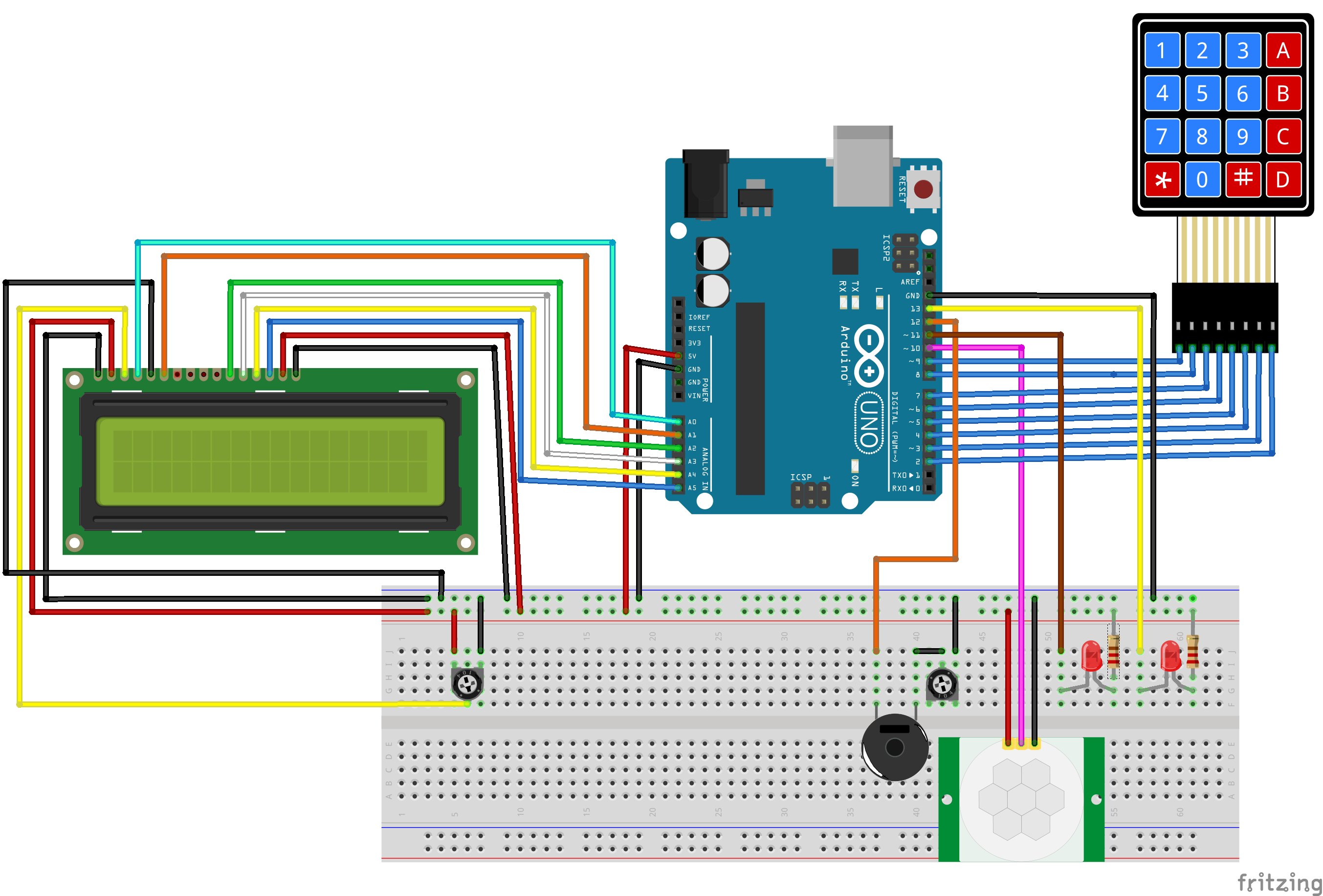
For this project, a motion detector alarm system based on an Arduino Uno was created. All of the components along with many more are available in the Elegoo Complete Starter Kit for Arduino R3. The system has the following features:- PIR motion sensor HC-SR501 to detect movement in the proximity of the device.- LCD display to show alarm state and show input from the keypad.- Membrane switch keypad 4x4 to arm and disarm the system.- Alarm with audible alert from an active buzzer and visual alert via a red LED- System power indicator with a greed LED.
I undertook this project to gain more experience with coding more complex embedded projects that require the use of state machine programming. The keypad must be capable of sending input signals, the LCD screen must refresh and the LED indicator must switch off and on all without blocking. The usual hello world blinky LED code in this case is insufficient. The libraries required are available for download in zip format from Elegoo here or they can be downloaded from online by searching for the component libraries online. All libraries are standard for the components.
When the device is powered it is initialized in the disarmed state. An LCD with adjust brightness and contrast via a potary potentiometer indicates the state of the system and allows the user to see the input of the membrane keypad. On start up, the LCD indicates that to arm the system press the * key. When armed, the devise polls the output from the PIR sensor to detect movement. The alarm() function checks if the device is armed, when armed and when motion is detected the active buzzer is turned on and a red LED is lit. The handleBuzz() function acts to change the frequency of the buzzer which can be adjusted by changing the check value of the buzzCycleCounter. The buzzer volume is adjustable via a rotary potentiometer. To disable the system, a 4 digit key code is entered. The input is visible on the LCD. The key is hardcoded in a variable, but could be changed by the user in later enhancement iterations to the design. The # key is used to send the key for evaluation while the * key will reset the input. The design of the UI was modeled after keypad entry systems which generally do not have a way to view the code entered. The systems make the assumption that the user know to either choose the # button to signal the end the input and submit the code.
Here is the final bread board prototype:
And here is the project in action:
Attached are the Fritzing diagram files and the code which was developed
There are few improvements on the todo list:- Use Eprom to allow user defined pass key. - add batter backup- Tune the PIR sensor to be most sensitive to movement in the field of view and distance from the sensor based on the location where the alarm will be installed. - Tune the time that the PIR sensor. Currently after movement is no longer detected there is a long delay before the PIR will alert again. This need to be reduced so that the alarm fires from the maximum amount of time possible while movement is detected.


Comments
Please log in or sign up to comment.