
Hardware components | ||||||
 |
| × | 1 | |||
| × | 2 | ||||
 |
| × | 2 | |||
 |
| × | 1 | |||
 |
| × | 1 | |||
 |
| × | 1 | |||
Software apps and online services | ||||||
 |
| |||||
| ||||||
| ||||||
| ||||||
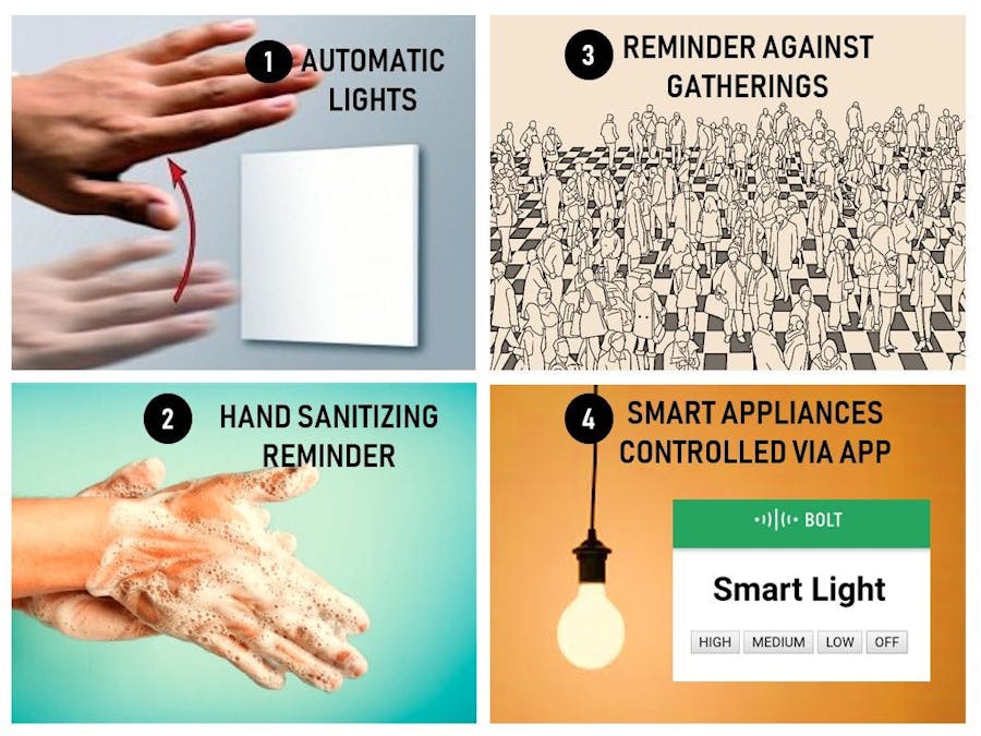
Severe Respiratory diseases, like the Corona virus Disease 2019 (COVID-19) spread when mucus or droplets containing the virus enter our body through our eyes, throat, or nose. Most often, this happens through our hands. Hands are also one of the ways that this virus spreads from one person to another. This virus can also spread from one person to another if a healthy person touches a surface that was previously touched by an infected person. Sadly, a lot of work that we regularly do requires us to touch several surfaces throughout the day. Moreover, unfortunately, a gathering/crowding is also an effective medium of transmission of this virus.
During this COVID-19 global pandemic, one of the most fundamental and crucial ways to prevent the spread of this virus is sanitizing our hands frequently. Also, using smart appliances and maintaining social distancing are some of the principal ways we can restrict the deadly virus spread.
This project is a complete automation setup for Home and Office for restricting the spread of COVID-19, using the Bolt IoT WIFI Module. This system includes automatic lighting with motion sensing using IR Sensor Module, Smart Appliances that can be controlled over the Bolt Cloud/App, frequent sanitizing reminder using a buzzer bell. Additionally, this system includes people to counter for the room to avoid overcrowding and maintain social distancing.
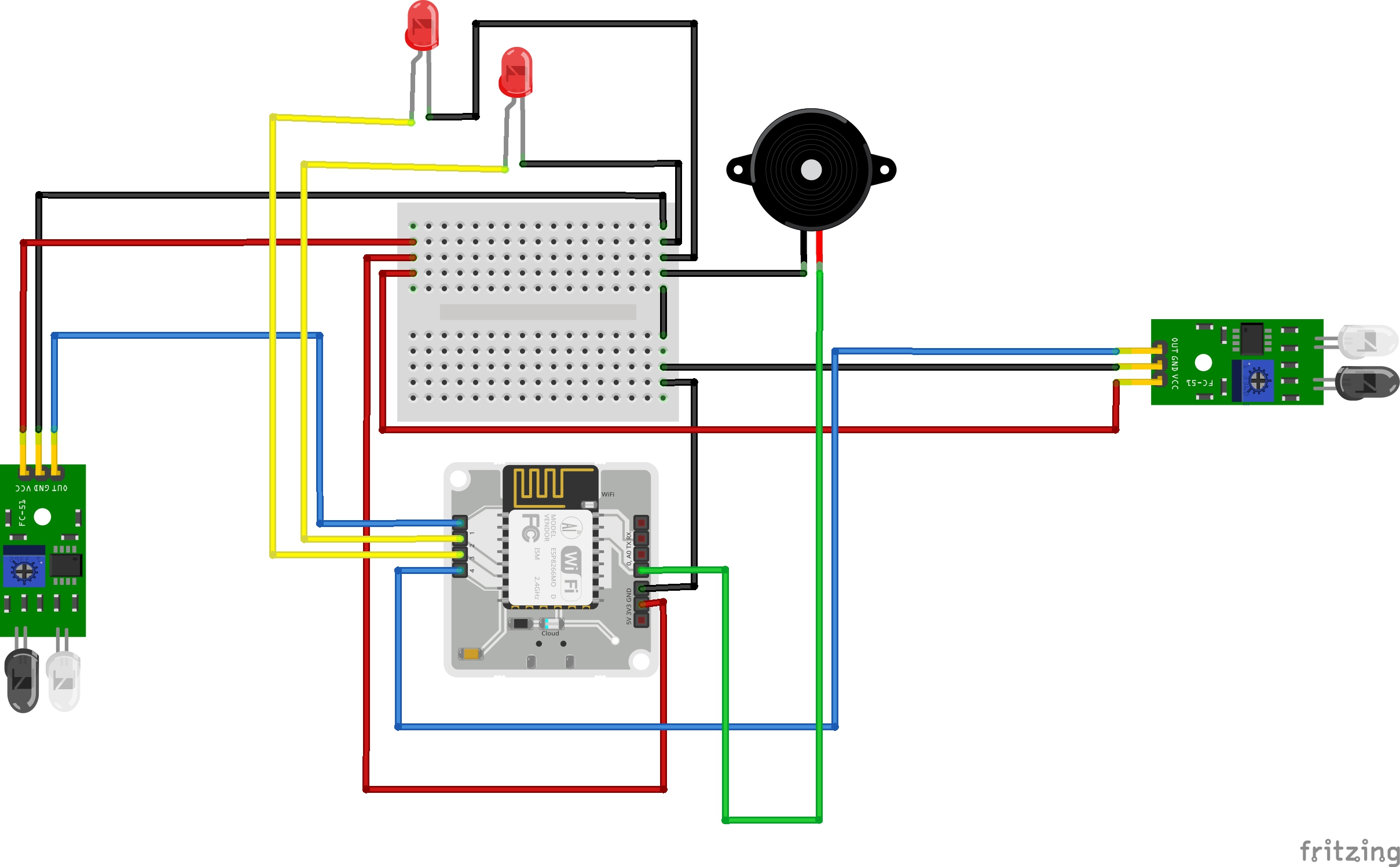
Hardware ConnectionsStep 1: ConnectingIR Sensor Modules to Bolt IoT WIFI Module
In first IR Sensor Module, VCC pin is connected with 3v3 pin of the Bolt WIFI Module, GND pin is connected with the GND of the Bolt WIFI Module, and the output pin in the IR Sensor Module is connected with digital pin 1 of the Bolt WIFI Module. (refer Figure 1)
Similar connections are made for the second IR Sensor Module, with the output pin of the module being connected to the digital pin 4 of the Bolt WIFI Module.
Step 2: ConnectingLEDs to Bolt IoT WIFI Module
We then connect the positive leg of the LED to the digital 2 pin of the Bolt WIFI Module negative leg of the LED into the ground pin of the Bolt WIFI Module.(refer Figure 2)
Similarly, another LED is connected to the Bolt WIFI Module using the ground pin and the digital pin 3.
Step 3:ConnectingPiezo Buzzer to Bolt IoT WIFI Module
Piezo Buzzer Connections are similar to that of LED. But, unlike LED there is no requirement of resistor in series with the buzzer. The longer pin is the positive pin and the shorter one is the negative one. The buzzer is connected to the digital 0 pin(refer Figure 3)
Step 4: The Complete Setup
The Complete hardware setup is given in Figure 4.
Step 1: Sign up/Sign in to the Bolt Cloud bolt
Step 2: Link your Bolt Device to the Bolt Cloud using the Bolt App.
Step 3: Create the product on Bolt Cloud, choose product type as Output Device and interface type as GPIO.
Step 4: After creating the product, select the recently created product and then click on configure icon.
Step 5: In the code configuration, write the for creating User Interface on the Bolt App to Control the Smart Appliances in the system. (refer: Code Section)
Step 6: Save and Exit the product configuration.
Step 7: Link the Bolt Module to the newly created product.
Step 8: We will also do Python Programming in Virtual Private Server (VPS). To know about BOLT IoT API and how to set up VPS for using alongside Bolt Cloud refer to the sections of API and Client Libraries in the Bolt IoT Documents.
Configuring Automatic LightsStep 1: Reading IR Sensors at Entry and Exit
Two IR Sensors are used in the room:
- Entry door
- Exit Door
IR Sensors detect the movement of people at the entry end exit doors.
Step 2: Counting the people in the room
The difference of count at the entry and exit doors gives the no. of people in the room.
The following code segment implements Step 1 and 2.
Step 3: AUTOMATIC TOUCH LESS Lights
If, people are present in the room, then, light glows. It is automatic and there is no need to make physical contact with the switches which may be virus contaminated surfaces.The following code snippet executes the same idea.(Figure 6)
Alert in case of Overcrowding
The Overcrowding alert has the following algorithm:
- Read IR Sensor at Entry and Exit
- Count number of people in the room
- Is the number less than/equal to 5
- If not, send Alert via Mail (using Mailgun)
- Wait for 60 seconds(1 min)
- Repeat the process
Mailgun is an Email automation service. It has a very powerful set of inbuilt functions for sending emails. Developers can process their email with the help of Mailgun API. To automate email using Mailgun:
- Open Mailgun in browser.
- Sign up and fill the necessary details.
- Verify your phone number and email ID.
- Then Sandbox domain > add recipients > invite new recipient > enter email ID.
- Then click on the sandbox ID generated and save the sandbox URL and private API key somewhere safely.
The following code snippet shows the configuring of email alert using Mailgun API.(Figure 7)
Hand Sanitizing Reminder
This reminder alerts the people in the room to wash the sanitize their hands every 1 hour. For this we use a variable count :
- Initialize count as 0
- Enter the infinite loop
- Increment count by 60 every 60 seconds(1 min.)
- If count is divisible by 3600 (seconds equivalent of 1 hour), then, print Reminder Message on terminal and Alert the user via a 5 second Buzzer Alarm.
The following code snippet implements the same.(Figure 8)
User Interface Design
The complete User Interface (refer Figure 9) for controlling the SMART APPLIANCES is designed using HTML Code. In the header, we include a JavaScript file which has some pre-defined function like digitalRead, digitalWrite etc. already hosted on the Bolt Cloud.(refer Code section)
The User Interface serves is used to control two output devices here:
- Smart Light (ON/OFF/ Brightness Variation)
- Buzzer (OFF only)
The only purpose to keep the buzzer ON in case of overcrowding is to make the user more alert and aware about social distancing norms. Thus for Buzzer only e OFF only feature has been designed in the App and it gives Buzzer Switch control to the user after alerting him/her for overcrowding in the room.
Once the complete system building was accomplished, the system was put in operation. The system read IR Sensor Data, counted number of people in the room, and printing it on terminal(refer Figure 10) and alerts were successfully obtained via both Email (refer Figure 11) and the system itself.
A short video that gives the project demonstration has been attached for better understanding of the project and the underlying thoughts and ideas.


Comments