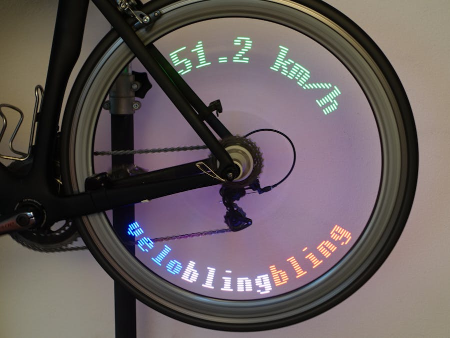
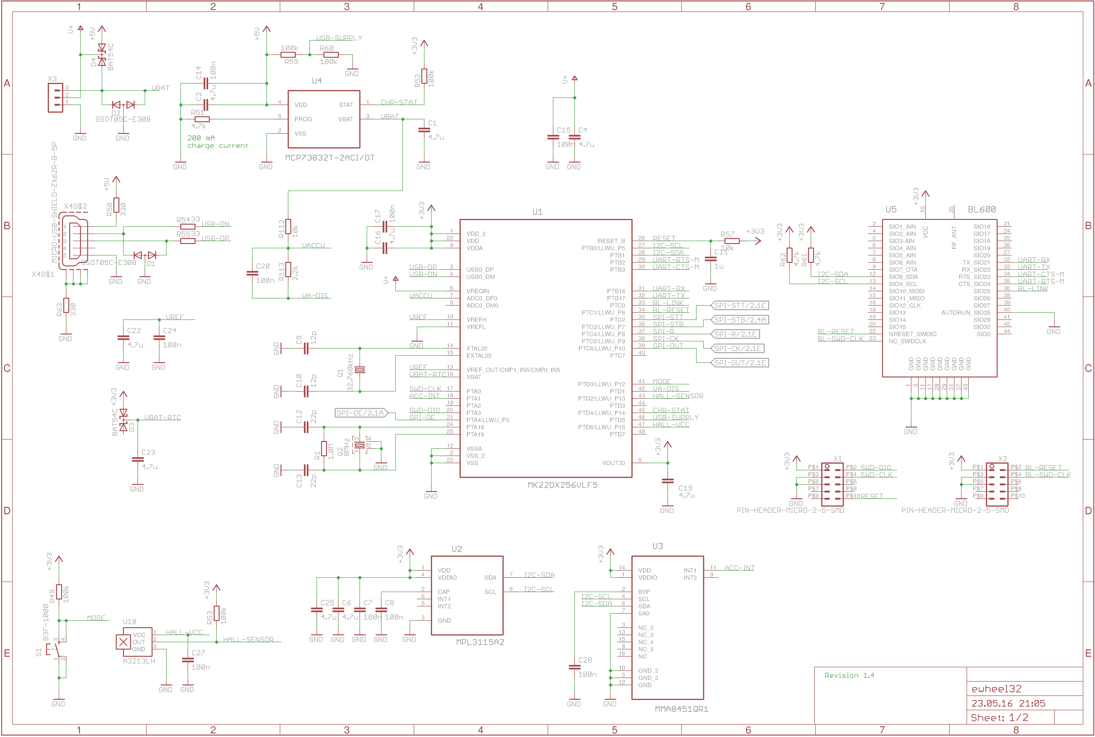
Yet another LED blinker (YALB). There are so many LED blinking projects out there, why another boring blinker? This is a different one. At least, it has more LEDs (32 RGB-LEDs) than an average blinker and the LEDs are controlled in real time (reaction time less than 270 μs to switch 96 LEDs). But there are more technical concepts to explore. I2C communication between main MCU and peripherals (pressure meter, accelerometer). Asynchronous serial communication between main MCU and the bluetooth subsystem. USB serial communication (terminal console) for testing purposes. Applied low power techniques (control and charging LiPol battery, real time clock, wake up through motion detection). Definitely a good project to learn how embedded systems work.
The project name Velo Bling-Bling consists of Velo (bicycle in French/Swiss or velocity in English) and Bling-Bling (flashy, ostentatious, or elaborate jewelry and ornamented accessories).
See also my Velo Bling-Bling blog.
PCB LayoutFor details see Velo Bling-Bling electronic design.
Assembly InstructionsThe flat no-leads packages for MPL3115A2 (LGA), NXP MMA8452Q Low-Power Accelerometer (QFN-16), and the BL600 Bluetooth module are difficult to manual solder, but these parts are optional and you can omit it if you are willing to forgo some features.
I use a pizza oven with a temperature controller for reflow soldering. You can get the oven and the reflow controller from eSTORE Beta Layout .
- Apply the solder paste to the top layer (use a stencil, some PCB manufacturers deliver laser stencils for free)
- Place the top side components
- Reflow solder the PCB in the pizza oven
- Place the bottom side components and manual solder each component
It is possible to mount the PCB direct onto the wheel spokes but it is better to use a mounting frame and potting the components in PUR (e.g. Electrolube UR 5048, Distrelec #956345). I prefer transparent PUR because in case of emergency you can dig out components and repair the electronics.
Glue the PCB to the lower frame part with 5 min epoxy.
Glue the upper part to the PCB. I propose to glue the USB connector and the pressure sensor enclosure. The PUR has a low viscosity and would soak into the connector and the pressure sensor (the hole has to be kept open). Of course, test the electronics before pouring.
You need a debug adapter and a programming software. There are many debug adapter available (e.g. from Segger), but they are expensive and you have to install drivers and software on your computer. I propose to use a Freescale/NXP Freedom Board e.g. FRDM-K22F or FRDM-K82F as a debug adapter / boot loader.
Quote from Freedom Board for Kinetis K22F Hardware (FRDM-K22F), Users Guide:
3.2.1 Debug interface Signals with SPI and GPIO capability are used to connect directly to the SWD of the K22F. These signals are also brought out to a standard 10-pin (0.05”) Cortex debug connector (J11). It is possible to isolate the K22F MCU from the OpenSDAv2 circuit and use J11 to connect to an off-board MCU. To accomplish this, cut the trace on the bottom side of the PCB that connects J7 pin 2 to J11 pin 4. This will disconnect the SWD_CLK pin to the K22F so that it will not interfere with communication to an off-board MCU connected to J7. The J11 header is populated by default. A mating cable, such as a Samtec FFSD IDC cable, can then be used to connect from the OpenSDAv2 of the FRDM-K22F to an off-board SWD connector.
You can still use the FRDM-K22F as a prototype board. You should solder a pinheader and plug a jumper if you want to use the FRDM-K22F as a prototype board.
- Connect the FRM-K22F J11 JTAG connector to the Velo Bling-Bling X1 connector
- Connect the FRM-K22F SDA Micro USB to the computer's USB interface, the FRDM-K22F acts as an USB mass storage (like a memory stick) and the windows computer sees an external drive.
- Copy the firmware binary to this drive.
For more details see the Velo Bling-Bling Firmware page.
Programming the Bluetooth ModuleThe Bluetooth module BL600 is programmed over the Velo Bling-Bling USB interface. The main MCU is the USB CDC and communicates over its UART with the BL600.
You can find the detailed instructions on Velo Bling-Bling Bluetooth Application page.
User Manual, TutorialSee Velo Bling-Bling User Manual.


.jpg?auto=compress%2Cformat&w=48&h=48&fit=fill&bg=ffffff)


_3u05Tpwasz.png?auto=compress%2Cformat&w=40&h=40&fit=fillmax&bg=fff&dpr=2)


Comments
Please log in or sign up to comment.